Exhaust gas treatment device and exhaust gas treatment system

A waste gas treatment device and waste gas technology, which are applied in the directions of gas treatment, combustion product treatment, combustion method, etc., can solve the problems of increasing initial cost and maintenance cost, and achieve the goal of reducing the number, promoting diffusion, and ensuring concentration uniformity. Effect

Inactive Publication Date: 2016-03-23
MITSUBISHI HEAVY IND LTD
View PDF4 Cites 0 Cited by
  • Summary
  • Abstract
  • Description
  • Claims
  • Application Information

AI Technical Summary

Problems solved by technology

[0023] However, considering that the air flow of the exhaust gas 12 supplied to the denitration catalyst layer 13 in the past has fluctuations (drift) in the inlet air flow conditions in the flue, it is necessary to install a plurality of injection nozzles in order to make the concentration of hydrogen chloride uniform. As a result, there are The problem of increased initial cost and maintenance cost

Method used


Image

  • Exhaust gas treatment device and exhaust gas treatment system
  • Exhaust gas treatment device and exhaust gas treatment system
  • Exhaust gas treatment device and exhaust gas treatment system

Examples


Embodiment 1

[0051] An exhaust gas treatment system to which an exhaust gas treatment device according to an embodiment of the present invention is applied will be described with reference to the drawings.

[0052] It should be noted that, due to the structure and Figure 5 The shown exhaust gas treatment systems have the same structure, so in this embodiment, only the structure of the exhaust gas treatment device will be described.

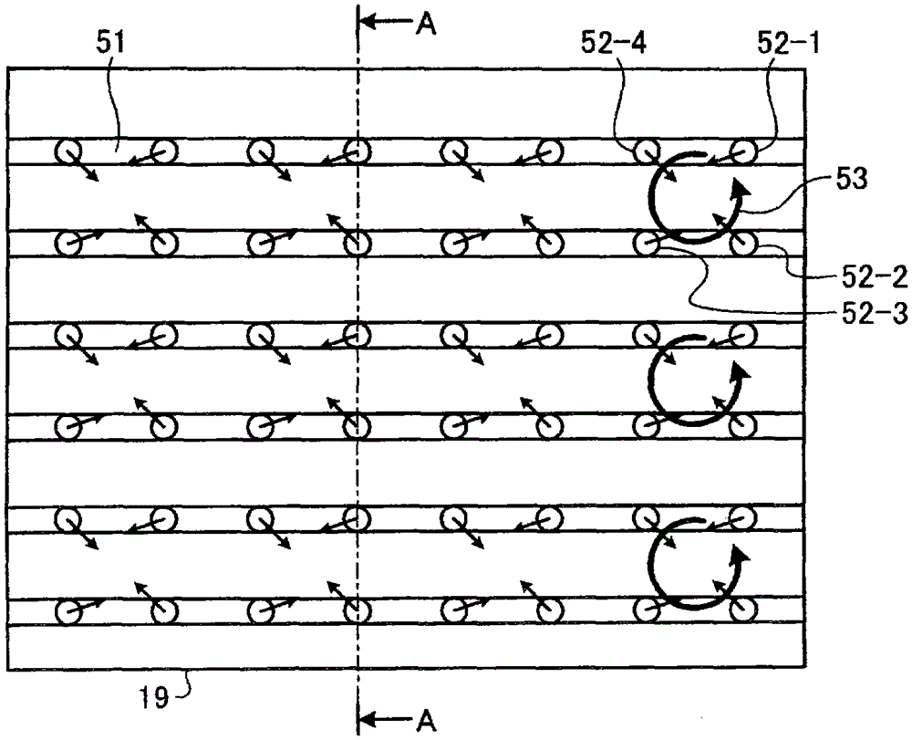
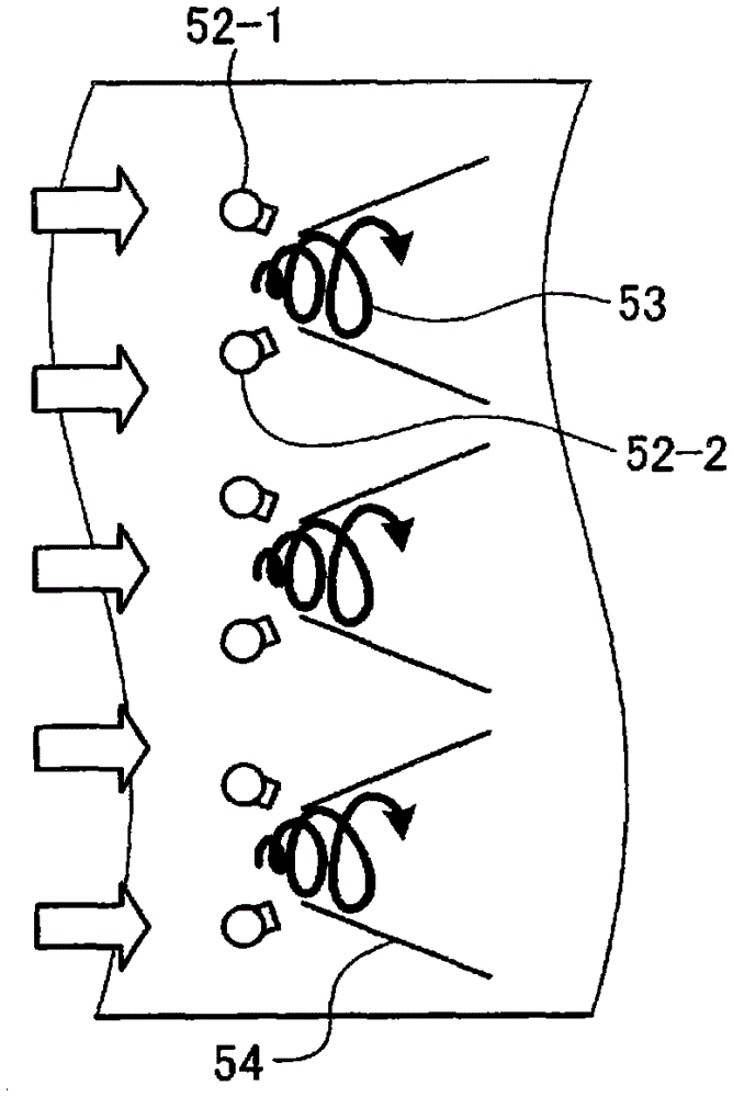
[0053] Picture 1-1 It is a schematic diagram showing the spray nozzle in the flue of the exhaust gas treatment device of the embodiment, Figure 1-2 is its A-A view. It should be noted that due to the structure of the exhaust gas treatment system and Figure 5 are the same, so their description is omitted.

[0054] Such as Picture 1-1 and Figure 1-2 As shown, the exhaust gas treatment device of this embodiment has at least one denitration catalyst layer, and the denitration catalyst layer removes nitrogen oxides in the exhaust gas 12 from the boiler 11...

Embodiment 2

[0062] An exhaust gas treatment device according to an embodiment of the present invention will be described with reference to the drawings.

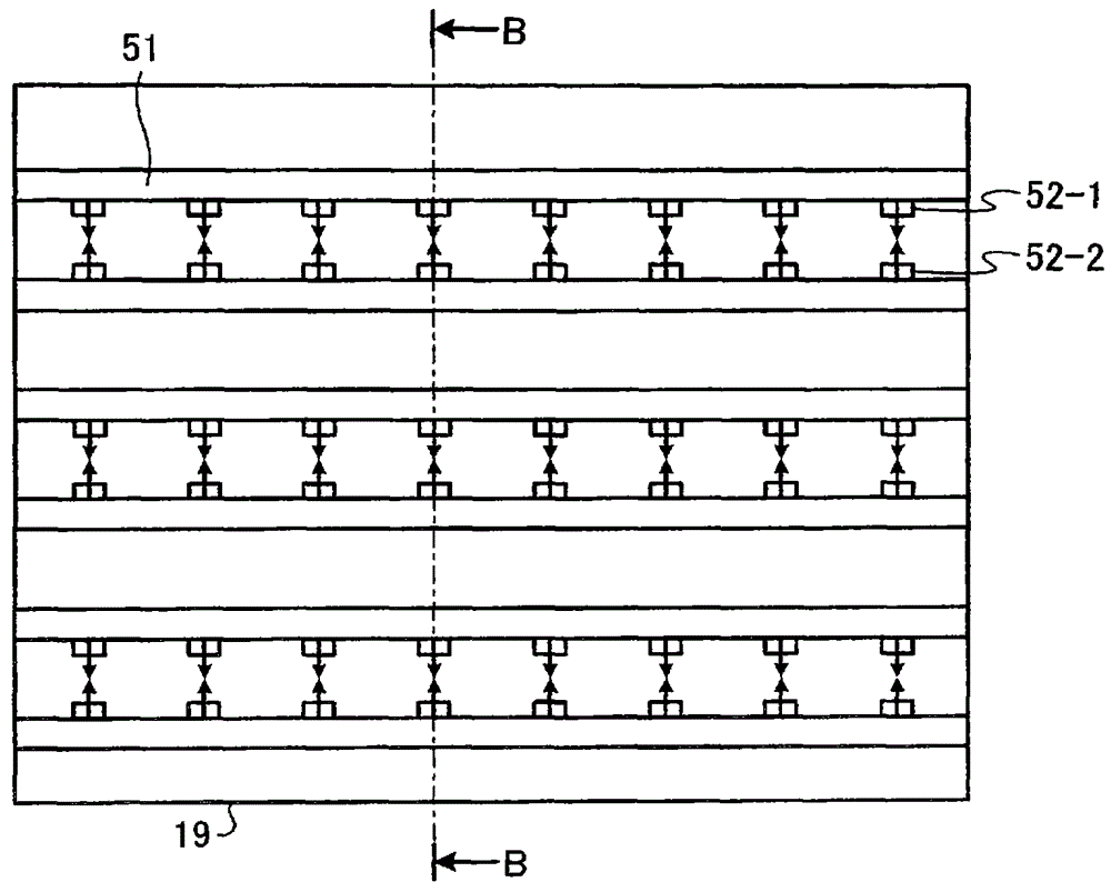
[0063] diagram 2-1 It is a schematic diagram showing the spray nozzle in the flue of the exhaust gas treatment device of the embodiment, Figure 2-2 is its B-B direction view. Figure 2-3 It is a schematic diagram showing the facing state of spray nozzles. It should be noted that due to the structure of the exhaust gas treatment system and Figure 5 are the same, so their description is omitted.

[0064] Such as diagram 2-1 , Figure 2-2 and Figure 2-3 As shown, in this embodiment, the gas diffusion promotion mechanism includes a spray pipe joint 51 arranged in the flue 19 and inserted perpendicularly to the gas flow direction of the flue 19, and a pipe joint 51 arranged on the spray pipe. The plurality of spray nozzles 52 of the joint 51 face each other, and collide the jet streams with each other.

[0065] In this example, i...

Embodiment 3

[0070] An exhaust gas treatment device according to an embodiment of the present invention will be described with reference to the drawings.

[0071] Figure 3-1 It is a schematic diagram showing the spray nozzle in the flue of the exhaust gas treatment device of the embodiment, Figure 3-2 is its C-C direction view, Figure 3-3 is a perspective view of a swirling diffuser. It should be noted that due to the structure of the exhaust gas treatment system and Figure 5 are the same, so their description is omitted.

[0072] Such as Figure 3-1 to Figure 3-3 As shown, in this embodiment, the gas diffusion promotion mechanism includes a spray pipe joint 51 arranged in the flue 19 and inserted perpendicularly to the gas flow direction of the flue 19, and a pipe joint 51 arranged on the spray pipe. The spray nozzle 52 of the joint 51 is provided with a swirling diffuser plate 55 on the opening side of the spray nozzle 52 to form a vertical vortex along the gas flow direction.

...


PUM


Abstract

An air pollution control apparatus includes at least one denitration catalyst layer for reducing the amounts of nitrogen oxides in flue gas from a boiler and oxidizing mercury with hydrogen chloride sprayed into the flue gas. Spraying pipe headers 51 are disposed in a flue gas duct 19. The spraying pipe headers 51 are inserted into the flue gas duct 19 and arranged in a direction orthogonal to the direction of a gas flow in the flue gas duct 19. At least four spray nozzles 52-1 to 52-4 are disposed on the spraying pipe header 51 to form a vertical vortex flow 53 in the gas flow direction. The diffusion of hydrogen chloride is thereby facilitated in a rapid manner. Therefore, the number of the nozzles can be reduced, and the uniformity of the concentration of hydrogen chloride at the location of the catalyst can be ensured even when the spacing between the nozzles is increased.

Description

technical field [0001] The present invention relates to an exhaust gas treatment device and an exhaust gas treatment system for treating exhaust gas discharged from a combustion device. Background technique [0002] For example, since exhaust gas discharged from a coal-fired boiler, which is a combustion device such as a thermal power plant, contains highly toxic mercury, various systems for removing mercury in exhaust gas have been considered conventionally. [0003] Generally, a coal-fired boiler is provided with a wet desulfurization device for removing sulfur components in exhaust gas. In the flue gas treatment equipment formed by attaching a desulfurization device to the boiler as a waste gas treatment device, it is known that when the chlorine (Cl) component in the waste gas increases, the divalent metallic mercury (Hg) soluble in water The proportion is increased, so that mercury is easily captured by the desulfurization device. [0004] Therefore, in recent years, ...

Claims


Application Information

Patent Timeline
Patent Type & Authority Patents(China)
IPC IPC(8): B01D53/94B01D53/50B01D53/64B01D53/86
CPCB01D53/64B01D53/501B01D53/56B01D53/8631B01D2251/108B01D2251/2062B01D2255/102B01D2255/20723B01D2255/20738B01D2255/20746B01D2255/20753B01D2255/20769B01D2255/20776B01D2257/302B01D2257/404B01D2257/602F23J2215/60
Inventor 坂田展康四条利久磨佐藤敏浩村上盛纪鹈饲展行野地胜己清泽正志
Owner MITSUBISHI HEAVY IND LTD
Why Eureka
Try Eureka