

Laser lap welding method for galvanized steel sheet
A technology of galvanized steel sheet and welding method, applied in laser welding equipment, welding equipment, welding/welding/cutting items, etc., can solve problems such as pinholes and bubble holes, achieve high speed and welding joints, excellent technical characteristics, avoid Effect of Welding Defects
- Summary
- Abstract
- Description
- Claims
- Application Information
AI Technical Summary
Problems solved by technology
Method used
Image

Examples
Embodiment 1
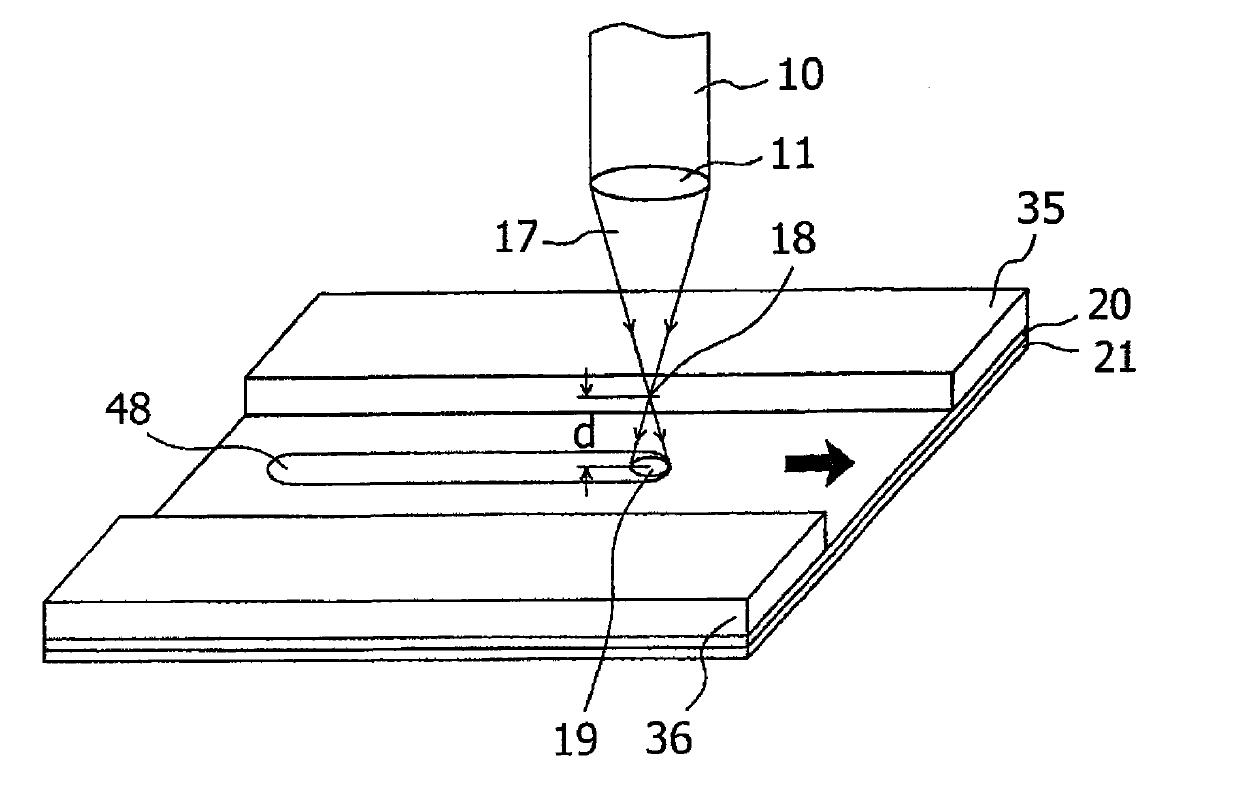
[0036] After that, in order to verify the relationship between laser power and laser spot diameter, galvanized steel sheets with a thickness of t=0.7mm were used, wherein the galvanized steel sheets were stacked one on top of the other without gaps, so that each galvanized layer As the interface between them, experiments were performed to evaluate keyhole formation, occurrence of zinc gas defects, and welding quality. The experiment was carried out under each spot diameter below, while gradually changing the laser power P (kW) and the laser travel speed v (m / min): (a) spot diameter (b) Spot diameter (c) Spot diameter (d) Spot diameter and (e) point diameter
[0037] In the experiment, DISECK laser oscillator manufactured by TRUMPF company (maximum output 10kW and transmission fiber diameter And the maximum output 16kW and transmission fiber diameter ), where the wavelength of the laser beam is in the range of 1000 to 1200 nm, which is suitable for optical fiber tr...
Embodiment 2
[0044] After that, under the same conditions as the above example, galvanized steel sheets with a thickness of t = 1.2mm were used, wherein the galvanized steel sheets were stacked one on top of the other without gaps so that each galvanized layer was used as a gap between them. Experiments were conducted to evaluate keyhole formation, presence of zinc gas defects, and weld quality. The experiment was carried out under each spot diameter below, while gradually changing the laser power P (kW) and the laser travel speed v (m / min): (a) spot diameter and (b) point diameter
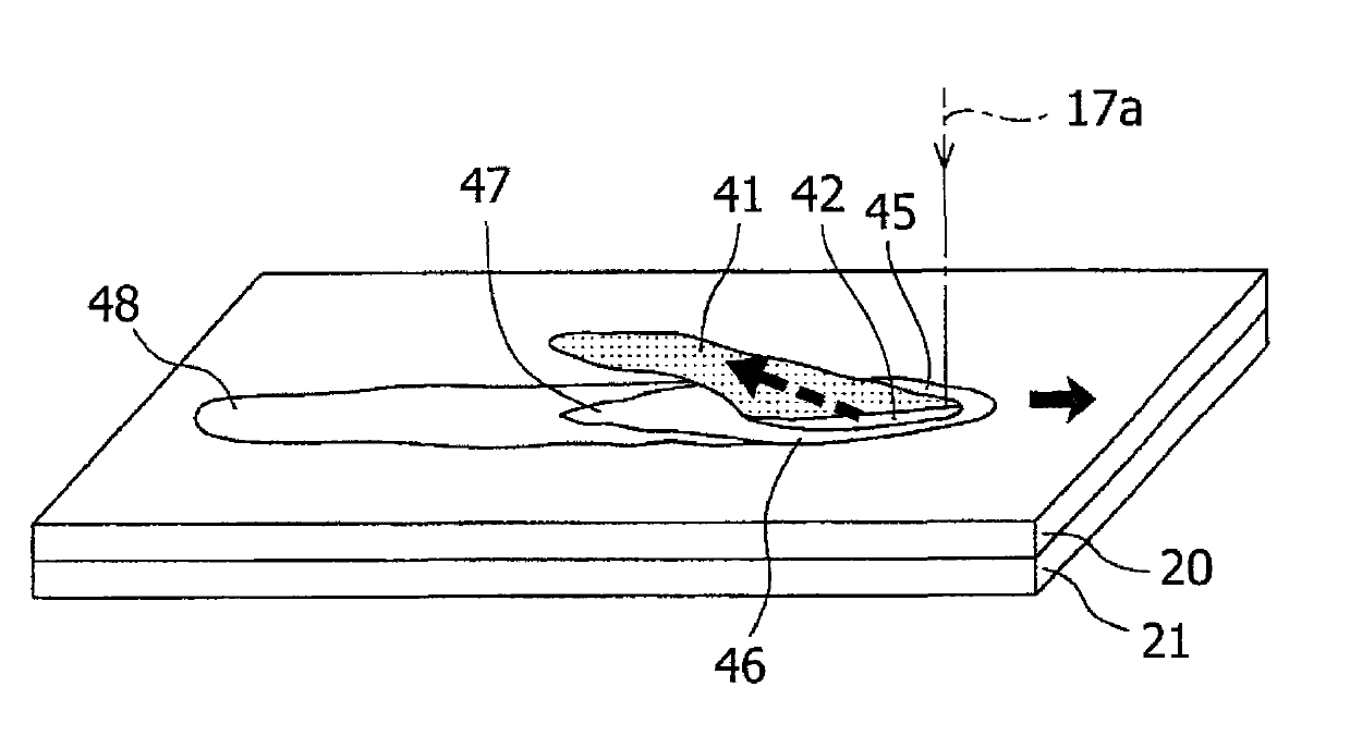
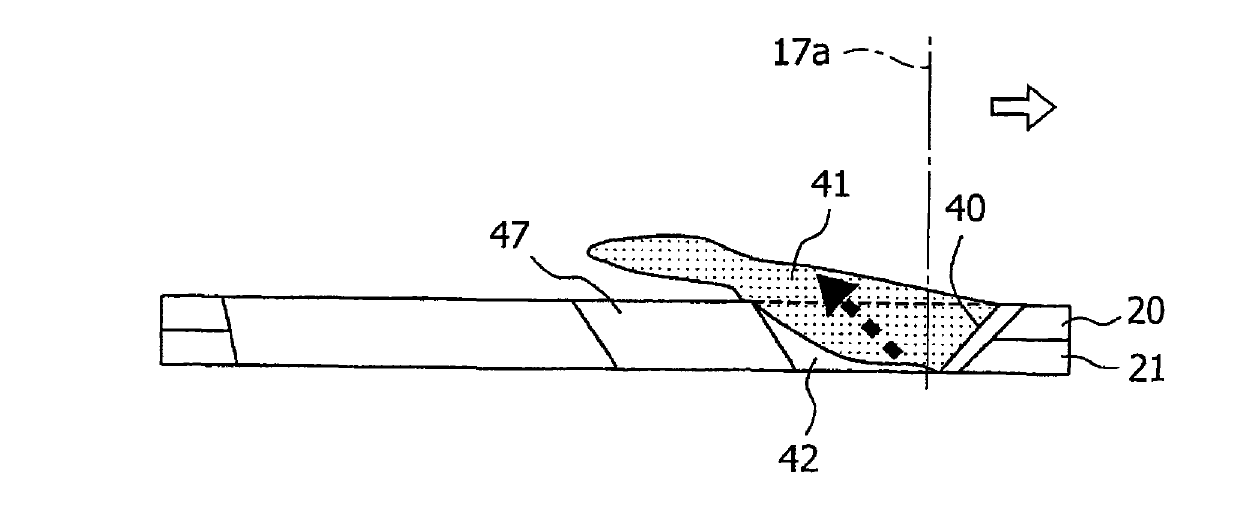
[0045] Figure 6 (a) to 6(b) show the experimental results. The symbols in each figure have the same meanings as those used in the above experiments. Although the number of samples is smaller than that at a thickness of 0.7 mm, approximately the same tendency is shown. Experiments are also sporadically at larger spot diameters than illustrated under, and at smaller spot diameters than shown next. f...
Embodiment 3
[0048] Afterwards, considering the above experimental results, galvanized steel sheets with a thickness of t = 0.6 mm were used, in which the galvanized steel sheets were stacked one on top of the other without gaps so that each galvanized layer served as a contact surface between them , so that experiments were performed to evaluate keyhole formation, occurrence of zinc gas defects, and welding quality. The experiment was carried out with a laser power P of 7kW at each of the following spot diameters, while changing the laser travel speed v (m / min): (a) spot diameter (b) Spot diameter and point diameter In this additional experiment, a fiber laser oscillator manufactured by TRUMPF (maximum output 7kW, transmission fiber diameter is 0.2mm, and the wavelength is 1070nm).
[0049] Figure 7 (a) to 7(c) show the experimental results. The symbols used here have the same meanings as those used in the above experiments. According to the previous experimental results, relat...
PUM
| Property | Measurement | Unit |
|---|---|---|
| boiling point | aaaaa | aaaaa |
| thickness | aaaaa | aaaaa |
| thickness | aaaaa | aaaaa |
Abstract
Description
Claims
Application Information