Method for manufacturing secondary battery and secondary battery

A secondary battery and manufacturing method technology, applied in the direction of lithium batteries, final product manufacturing, battery pack components, etc., can solve problems such as difficulty in forming uniform bending and reduction in mechanical strength of thin foils

Inactive Publication Date: 2011-07-13
PANASONIC CORP
View PDF6 Cites 2 Cited by
  • Summary
  • Abstract
  • Description
  • Claims
  • Application Information

AI Technical Summary

Problems solved by technology

[0009] However, in the above-mentioned method, if the current collectors constituting the positive electrode plate 71 and the negative electrode plate 72 are thinned (for example, the film thickness is 20 μm or less), the mechanical strength of the thin foil itself is reduced, so even if the positive electrode plate 71 and the negative electrode plate are pressed, The end portions 71a, 72a of the negative electrode plate 72 are also difficult to form evenly bent flat portions.

Method used


Image

  • Method for manufacturing secondary battery and secondary battery
  • Method for manufacturing secondary battery and secondary battery
  • Method for manufacturing secondary battery and secondary battery

Examples


Embodiment 1

[0074] (1) Production of positive plate

[0075] First, 85 parts by weight of lithium cobaltate powder was prepared as a positive electrode active material, 10 parts by weight of carbon powder was prepared as a conductive material, and 5 parts by weight of polyvinylidene fluoride (PVdF) was prepared as a binder. Then, the prepared positive electrode active material, conductive material and binding material are mixed to prepare the positive electrode mixture coating.

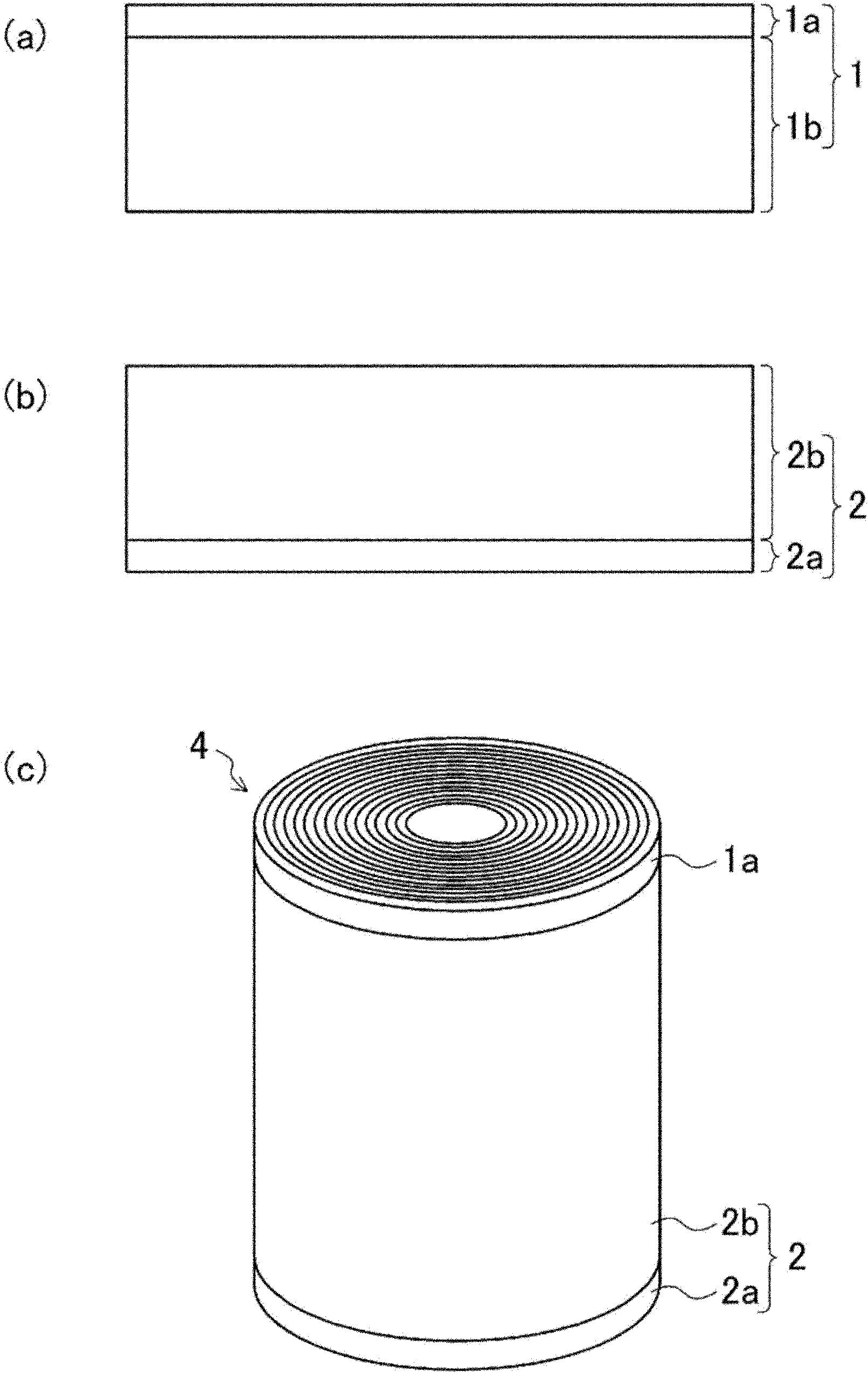
[0076] Next, the positive electrode mixture paint was applied to both surfaces of the positive electrode current collector of an aluminum foil having a thickness of 15 μm and a width of 56 mm, and the positive electrode mixture paint was dried. Then, the positive electrode mixture layer 1 b coated with the positive electrode mixture paint was rolled to form a positive electrode plate 1 with a thickness of 150 μm. At this time, the width of the positive electrode mixture layer 1 b was 50 mm, and the width of the ...

Embodiment 2

[0094] (1) Production of positive plate

[0095] First, 85 parts by weight of lithium cobaltate powder was prepared as a positive electrode active material, 10 parts by weight of carbon powder was prepared as a conductive material, and 5 parts by weight of polyvinylidene fluoride (PVdF) was prepared as a binder. Then, the prepared positive electrode active material, conductive material, and binder were mixed to prepare a positive electrode mixture coating.

[0096] Next, the positive electrode mixture paint was applied to both surfaces of the positive electrode current collector of an aluminum foil having a thickness of 15 μm and a width of 83 mm. After the positive electrode mixture paint was dried, the positive electrode mixture layer 1 b was rolled to produce a positive electrode plate 1 with a thickness of 83 μm. At this time, the width of the positive electrode mixture layer 1 b was 77 mm, and the width of the non-coated portion 1 a of the positive electrode mixture was ...


PUM

PropertyMeasurementUnit
widthaaaaaaaaaa
thicknessaaaaaaaaaa
thicknessaaaaaaaaaa

Abstract

The present invention provides a method for manufacturing a secondary battery, which comprises: a step of preparing an electrode group (4) in which a positive electrode plate (1) and a negative electrode plate (2) are arranged opposite to each other via a porous insulating layer in such a manner that an end portion (1a, 2a) of at least one of the positive electrode plate (1) and the negative electrode plate (2) projects beyond the porous insulating layer; a step of preparing a collector plate (10), a major surface of which is provided with a plurality of projections (11) each having an apex; a step of bringing the end portion (1a, 2a) of the electrode plate projecting beyond the porous insulating layer into contact with the other major surface of the collector plate (10); and a step wherein a projection (11) is melted by an arc discharge toward the apex of the projection (11) and the end portion (1a, 2a) of the electrode plate and the collector plate (10) are welded to each other by a molten member (12) that is the molten projection (11).

Description

technical field [0001] The present invention relates to a method for manufacturing a secondary battery having an electrode group with a so-called "tabless structure", a current collector plate used in the manufacturing method, and a secondary battery having an electrode group with a tabless structure. Background technique [0002] With the miniaturization of portable electronic equipment, lithium-ion secondary batteries and nickel-metal hydride storage batteries are widely used as their power sources. In recent years, these batteries have been used as power sources that require vibration resistance and high current, such as electric tools and hybrid vehicles. Also attracted much attention. Therefore, there is an increasing demand for small, lightweight and high-output secondary batteries regardless of the shape of the battery, such as a cylindrical shape or a flat shape, in order to be able to cope with various types of use equipment. [0003] The electrode group with no ta...

Claims


Application Information

Patent Timeline
Patent Type & Authority Applications(China)
IPC IPC(8): H01M2/26H01M10/05H01M50/528H01M50/534H01M50/538H01M50/54
CPCY02E60/12H01M2/263H01M2/266Y10T29/49211Y10T29/49108Y02E60/10H01M50/538H01M50/54Y02P70/50H01M50/534H01M10/052
Inventor 柳沼裕典野野下孝神月清美加藤诚一
Owner PANASONIC CORP
Why Eureka
Try Eureka