Energy-saving consumption-reducing UV mould press

A technology for molding presses and workbenches, which is used in printing presses, rotary printing presses, general parts of printing machinery, etc., can solve the problems of large machine space occupation, large influence of production product deformation, and large environmental impact of temperature and ozone.

Pending Publication Date: 2018-05-15
珠海市瑞明科技有限公司
View PDF0 Cites 3 Cited by
  • Summary
  • Abstract
  • Description
  • Claims
  • Application Information

AI Technical Summary

Problems solved by technology

[0002] At present, the UV molding machine basically uses the mechanical structure of the coating machine, and the UV high-pressure UV mercury lamp is added to cure the UV varnish. This type of equipment has the following defects: 1. The machine takes up a lot of space, and the basic length is 10 meters. 2. The overall power of the machine is high, the power consumption is high, and the cost per unit product is high; 3. The ultraviolet high-pressure UV mercury lamp emits a lot of infrared energy when it is working, and the additional heat is large, which has a great impact on the deformation of the produced product. At the same time, it has a great impact on the working environment, and the generated temperature and ozone have a great impact on environmental protection.

Method used


Image

  • Energy-saving consumption-reducing UV mould press
  • Energy-saving consumption-reducing UV mould press
  • Energy-saving consumption-reducing UV mould press

Examples


Embodiment Construction

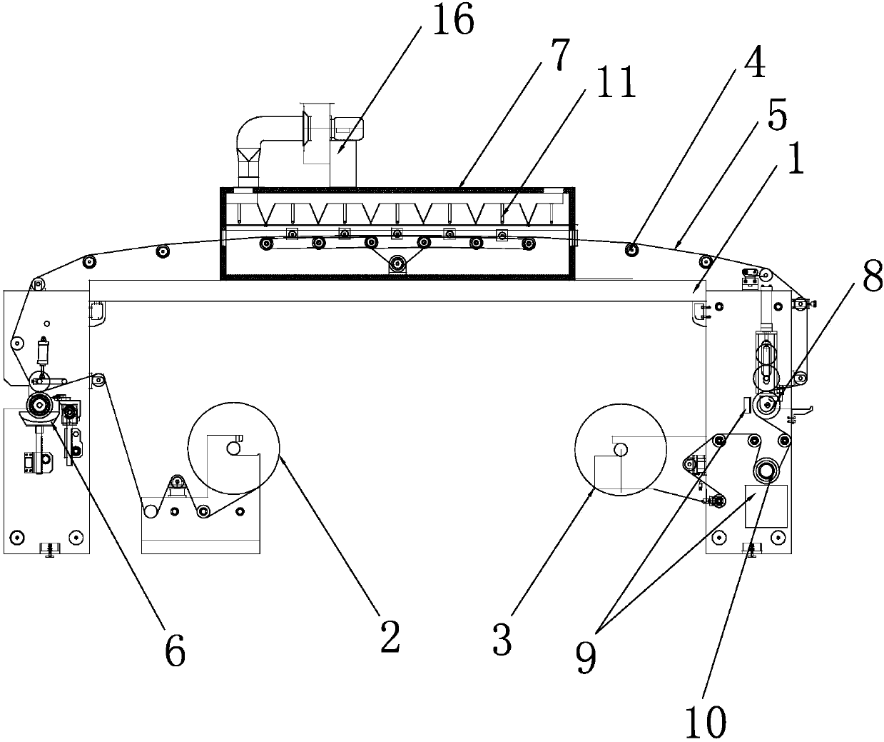
[0020] see figure 1 , an energy-saving and consumption-reducing UV molding machine of the present invention includes a worktable 1 and an unwinding unit 2 and a winding unit 3 arranged on the working table 1, and the unwinding unit 2 and the winding unit 3 are connected by a transmission Roller 4 conveys original film 5, and described workbench 1 is provided with coating tank 6, drying channel 7, nickel plate plate roll 8, UV LED lamp 9 and cooling roll 10 successively along the conveying direction of original film 5, and described nickel plate Version roller 8, cooling roller 10 and driving roller 4 are synchronously driven.

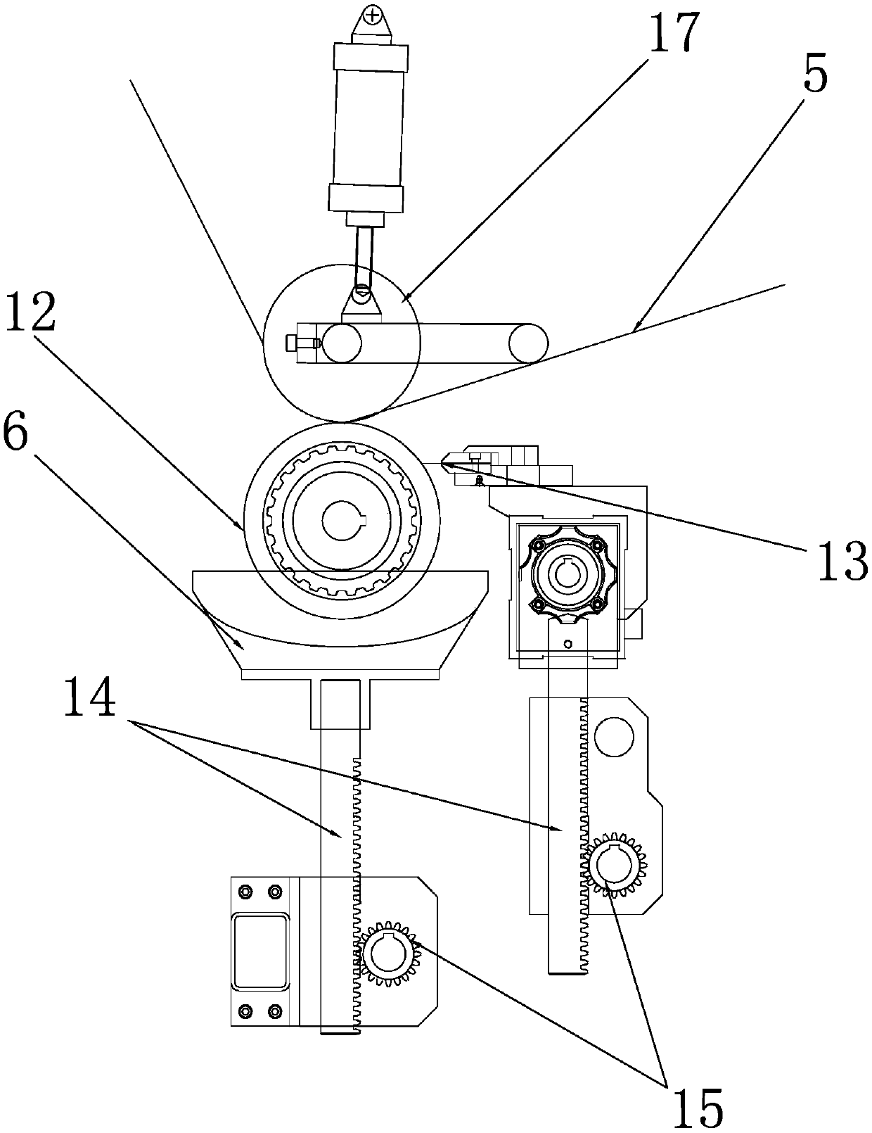
[0021] see further figure 2 , the coating tank 6 is filled with UV paint for coating the original film 5, and the workbench 1 is located above the coating tank 6 and is provided with an anilox roller 12 synchronously driven with the drive roller 4, and the anilox roller The lower end of 12 extends into the UV coating in the coating tank 6, and the or...


PUM


Abstract

The invention discloses an energy-saving consumption-reducing UV mould press. The energy-saving consumption-reducing UV mould press comprises a workbench as well as an unrolling unit and a rolling unit, which are arranged on the workbench, wherein a raw film is transmitted between the unrolling unit and the rolling unit through a transmission roller; the workbench is sequentially equipped with a coating slot, a drying tunnel, a nickel plate roller, an UV LED lamp and a cooling roller in a transmission direction of the raw film; the nickel plate roller, the cooling roller and the transmission roller synchronously transmit; and UV paint used for coating the raw film is contained in the coating slot. The mould press is reasonable in layout; the raw film is coated through the UV paint in the coating slot, and an infrared-ray heating tube is used for performing radiation heating on UV paint, so that heat loss is reduced; the nickel plate roller is used for transfer-printing patterns onto UVpaint on the raw film, and the UV LED lamp is used for curing the UV paint; and the UV LED lamp is a cold light source, and is free of thermal radiation, the temperature rise of the radiated productsurface is low, thermal harm on products is not caused, and the cooling roller performs cooling on the raw film, so that the integral energy consumption is relatively low.

Description

technical field [0001] The invention relates to the technical field of molding, in particular to an energy-saving and consumption-reducing UV molding machine. Background technique [0002] At present, the UV molding machine basically uses the mechanical structure of the coating machine, and the UV high-pressure UV mercury lamp is added to cure the UV varnish. This type of equipment has the following defects: 1. The machine takes up a lot of space, and the basic length is 10 meters. 2. The overall power of the machine is high, the power consumption is high, and the cost per unit product is high; 3. The ultraviolet high-pressure UV mercury lamp emits a lot of infrared energy when it is working, and the additional heat is large, which has a great impact on the deformation of the produced product. At the same time, it has a great impact on the working environment, and the temperature and ozone generated have a great impact on environmental protection. Contents of the invention...

Claims


Application Information

Patent Timeline
Patent Type & Authority Applications(China)
IPC IPC(8): B41F19/02B41F19/00B41F23/04
CPCB41F19/02B41F19/001B41F23/0483
Inventor 王丹王强罗敏
Owner 珠海市瑞明科技有限公司
Why Eureka
Try Eureka