Optical fiber current transformer for three-phase common super-fluorescence optical fiber light source

A current transformer and fiber optic light source technology, applied in the direction of voltage/current isolation, etc., can solve the problems of large optical path loss, rotation sensitivity, limited life, etc., meet the requirements of low output power of the light source, reduce the transformation ratio error of the transformer, The effect of reducing the requirement for temperature control accuracy

Inactive Publication Date: 2011-07-20
BEIHANG UNIV
View PDF5 Cites 37 Cited by
  • Summary
  • Abstract
  • Description
  • Claims
  • Application Information

AI Technical Summary

Problems solved by technology

The main problems in the engineering application of this scheme are: it is necessary to ensure the consistency of the two 1 / 4 wave plates, there is a certain degree of difficulty in the process, and it is seriously affected by vibration and Shupe effect; it is sensitive to rotation due to the Sagnac effect ; The current sensitivity is only half of the reflective fiber optic current transformer
[0005] However, in the existing technical solutions, the reflective Sagnac-type fiber optic current transformer has problems such as large optical path loss and low utilization rate of signal light. Since superluminescent light-emitting diodes (SLD) are generally used as light sources, their efficiency is low and the light output power is not high. High and limited life, not enough for power system applications

Method used


Image

  • Optical fiber current transformer for three-phase common super-fluorescence optical fiber light source
  • Optical fiber current transformer for three-phase common super-fluorescence optical fiber light source
  • Optical fiber current transformer for three-phase common super-fluorescence optical fiber light source

Examples


Embodiment Construction

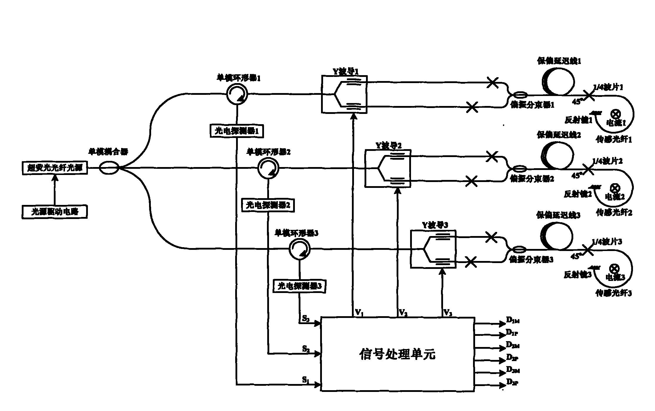
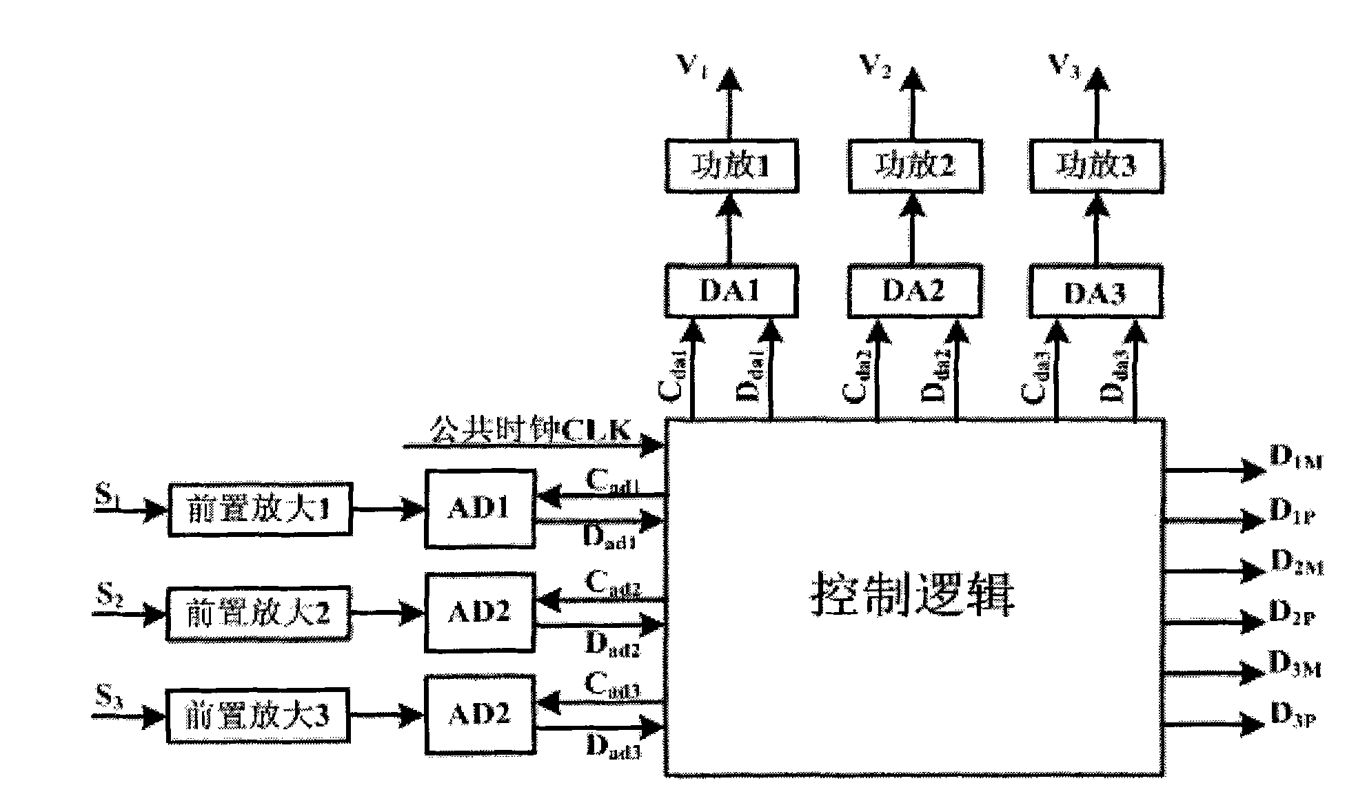
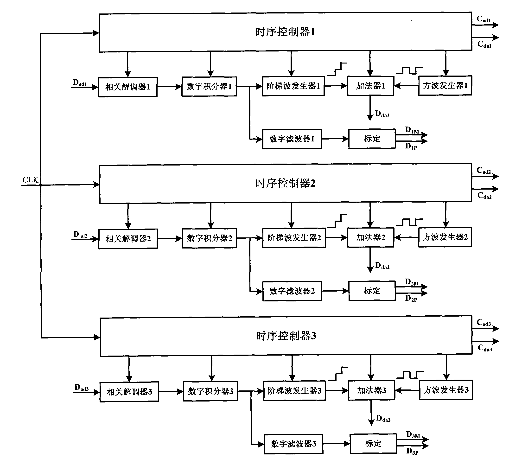
[0028] The embodiment of the present invention provides a fiber-optic current transformer with a three-phase shared super-fluorescent fiber-optic light source, which can reduce the transformation ratio error of the transformer caused by the center wavelength drift of the light source and the requirements for the temperature control accuracy of the light source, and the optical path loss is small, and the signal The light utilization rate is high, and the requirements for the output power of the light source are lower under the same signal-to-noise ratio requirements; at the same time, a mixed-polarization scheme for a three-phase shared light source is proposed, which is beneficial to suppress the polarization non-reciprocity error caused by birefringence, and effectively The utilization rate of signal light is improved, the optical path structure is simplified, the optical path loss is reduced, and the signal-to-noise ratio of the system is improved.

[0029] In order to bette...


PUM


Abstract

The embodiment of the invention provides an optical fiber current transformer for a three-phase common super-fluorescence optical fiber light source SFS; the current transformer comprises a super-fluorescence optical fiber light source SFS, a 1*3 single-mould coupler, a three-port single-module circulator, a Y waveguide integrated optical phase modulator, a polarization beam splitter, a polarization-maintaining delay line, a 1 / 4 wave plate, a sensing optical fiber, a reflection mirror, an optical-electric detector, a light source driving circuit and a signal processing unit, wherein the lightemitted by the super-fluorescence optical fiber light source is divided into three parts through the 1*3 single-mould coupler for respectively providing the light power input to each phase transformer; and the combination of the three-port single-mould circulator, the Y waveguide integrated optical phase modulator and the polarization beam splitter is adopted to realize the low consumption designof the optical path. The transformation ratio error of the transformer caused by the central wavelength shifting of the light source can be reduced through the current transformer, the demand for thelight source temperature control precision is reduced, and the service life of the transformer is prolonged; moreover, the optical fiber current transformer has small optical path consumption, high signal optical utilization ratio and relatively lower requirement for the light source output power with the same signal to noise ratio demand.

Description

technical field [0001] The invention relates to the field of optical fiber current transformers, in particular to an optical fiber current transformer with three phases sharing a super fluorescent optical fiber light source. Background technique [0002] The current transformer is one of the most important high-voltage equipment in the power system. With the continuous improvement of the voltage level of the power system, the traditional electromagnetic current transformer has exposed inherent shortcomings in terms of insulation, bandwidth, dynamic range, output interface, safety, weight, volume, etc., and based on the Faraday (Faraday) effect The Sagnac fiber optic current transformer has outstanding advantages in these aspects and is the most promising solution for high voltage and large current measurement. [0003] The Sagnac fiber optic current transformer makes full use of the non-reciprocity of the Faraday effect and the reciprocity of external interference, and dete...

Claims


Application Information

Patent Timeline
Patent Type & Authority Applications(China)
IPC IPC(8): G01R15/24
Inventor 王夏霄李传生张春熹于佳冯秀娟
Owner BEIHANG UNIV
Why Eureka
Try Eureka