Measurement system for motion parameters of high-speed motion object

A technology of object movement and measurement system, applied in weapons testing, weapon accessories, offensive equipment, etc., can solve the problems of unsuitable small-caliber projectile velocity measurement, high price, large equipment, etc., to reduce measurement costs, low prices, and yield. high effect

Inactive Publication Date: 2011-07-27
ZHONGBEI UNIV
View PDF10 Cites 21 Cited by
  • Summary
  • Abstract
  • Description
  • Claims
  • Application Information

AI Technical Summary

Problems solved by technology

However, this speed measurement method has many disadvantages, such as huge equipment, expensive price, and it is not suitable for the measurement of the velocity of small-caliber projectiles, etc.

Method used


Image

  • Measurement system for motion parameters of high-speed motion object
  • Measurement system for motion parameters of high-speed motion object
  • Measurement system for motion parameters of high-speed motion object

Examples


Embodiment 1

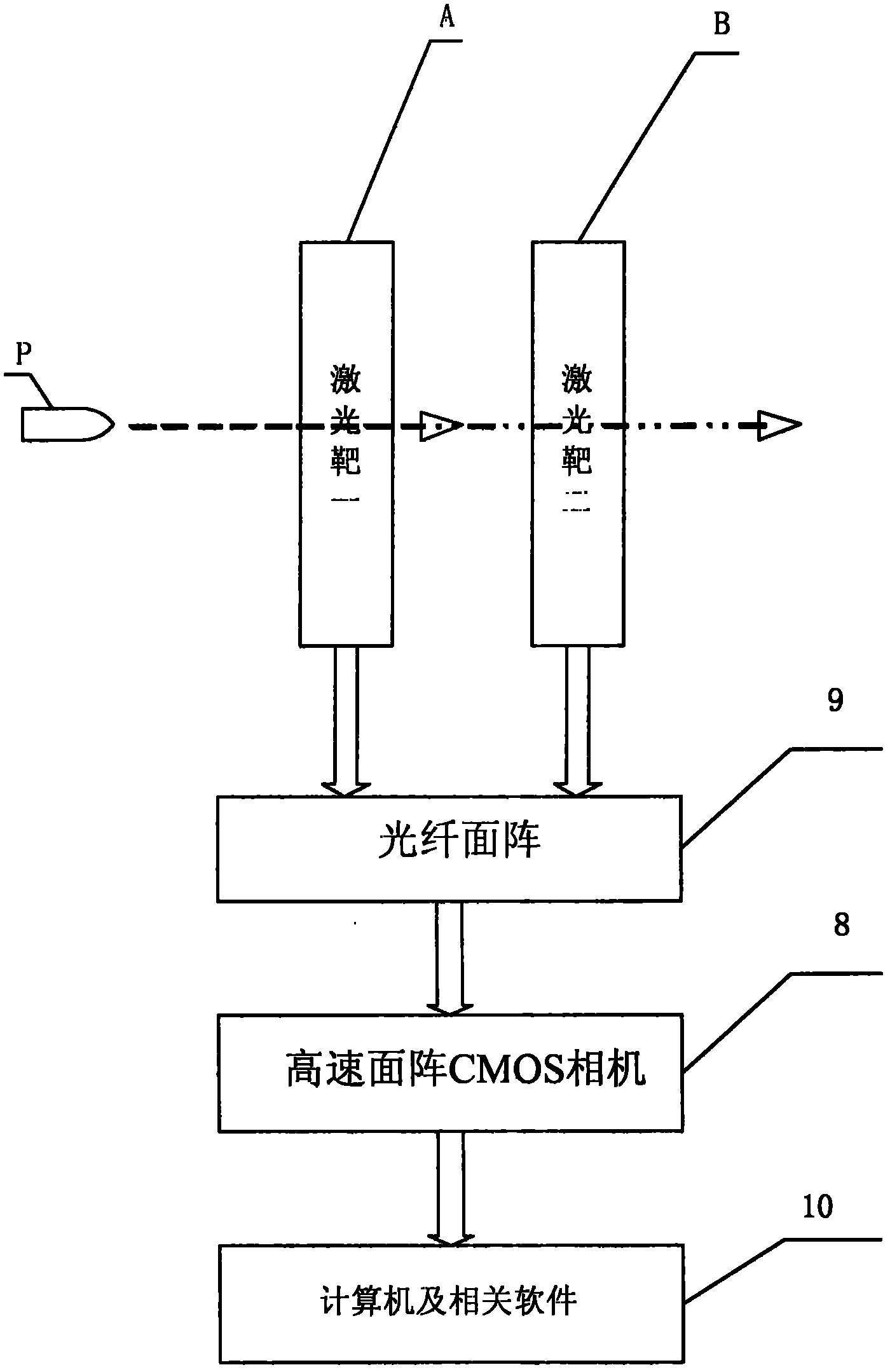
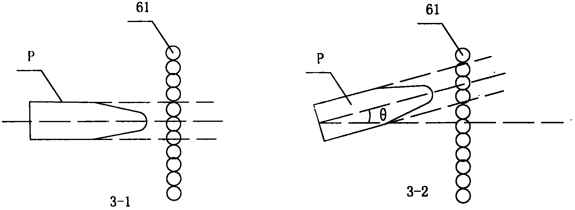
[0017] Such as figure 1 Shown is the schematic diagram of the test system structure of the present invention, including laser target A and laser target B, each of which forms two coplanar parallel laser light curtains in laser target A and laser target B, and the propagation direction of the two parallel laser light curtains They are perpendicular to each other; laser target A and laser target B are connected to the optical fiber array 9 through an optical fiber. When a moving object passes through the parallel laser light curtain, part of the laser light curtain is blocked, causing the luminous flux in the optical fiber array to change. It is collected by an optical signal collection device (such as a high-speed area array CMOS camera 8) and transmitted to a computer 10. By processing the collected images, the speed, coordinates, dispersion and motion posture of the moving object when passing through the light curtain can be obtained and other parameters, and displayed by th...

Embodiment 2

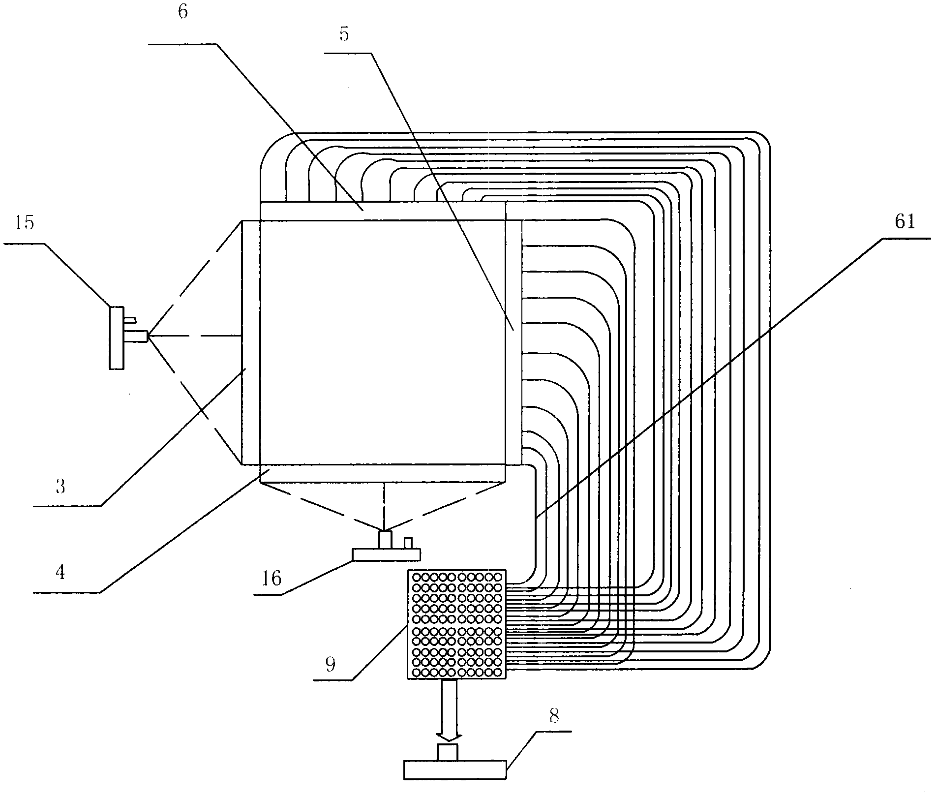
[0019] This embodiment introduces a specific implementation method. First, a cube target frame is made, and the specific size is determined by actual needs. Two laser targets A and B are placed vertically on the cube target frame. The target surfaces of the two laser targets are parallel, and the distance S between the targets is as follows: figure 2 Shown is a schematic diagram of the structure of the laser target of the present invention. Taking the laser target as an example A for illustration, each laser target has parallel laser light curtains in the X-axis direction and the Y-axis direction, and the parallel laser light curtains in each direction are made of laser light. Transmitters 15 and 16, Fresnel lenses 3 and 4 and optical fiber line array 61 are composed. Also refer to Figure 4 , the laser transmitter 15 is mounted on Figure 4 The position of 015 on the target frame, the Fresnel lens 3 is installed on the position of 03 on the target frame, and the laser transmit...


PUM


Abstract

The invention discloses a measurement system for motion parameters of a high-speed motion object. The measurement system comprises a laser target (A) and a laser target (B), wherein two coplanar parallel laser screens are formed in the laser target A and the laser target B respectively; the direction of propagation of the two parallel laser screens is perpendicular to each other; the laser target (A) and the laser target (B) are connected with an optical fibre face array (9) through optical fibres; when passing through the parallel laser screens, the motion object blocks a part of laser screens to make luminous flux in the optical fibre face array changed; the variable quantity is acquired by an optical signal acquisition device and transmitted to a computer (10); and the parameters such as a speed, coordinates, and scattering and motion gestures when the motion object passes through the screens can be obtained by processing an acquired image and displayed on a display. The measurement system is low in cost, simple in operation and high in precision and can carry out all-day continuous measurement.

Description

technical field [0001] The patent of the present invention relates to the technical field of measuring the motion parameters of high-speed moving objects (projectiles, fragments, etc.) by laser targets, and in particular to a measurement system for measuring the motion parameters of high-speed moving objects, including the coordinates, speed, dispersion, deflection angle, Pitch angle, motion attitude and other parameters. Background technique [0002] In the development and production of weapons, shooting training and compilation of shooting tables, it is necessary to measure the motion parameters of projectiles frequently. At present, there are mainly two types of measurement of motion parameters of high-speed moving objects: contact and non-contact. The traditional measurement method is to erect a hard paper target on a predetermined trajectory, and after shooting a certain number of times according to relevant standards, manually measure the bullet holes left on the pape...

Claims


Application Information

Patent Timeline
Patent Type & Authority Applications(China)
IPC IPC(8): F41A31/00
Inventor 李仰军郝慧艳王小燕王艳红刘新刚赵慧明王楠楠周汉昌王高
Owner ZHONGBEI UNIV
Why Eureka
Try Eureka