
Compressed air automobile

A technology of compressing air and compressed gas cylinders, which is applied to vehicle parts, pneumatic power devices, engines with one-way flow principle, etc., can solve the problems of oil consumption, energy shortage, human hazards, etc., and achieve the effect of simple manufacturing procedures

Inactive Publication Date: 2011-08-03
孙风举
View PDF5 Cites 0 Cited by
  • Summary
  • Abstract
  • Description
  • Claims
  • Application Information

AI Technical Summary

Problems solved by technology

[0002] At present, the known vehicle engine is powered by fuel oil, which consumes a large amount of oil, and the exhaust gas discharged after combustion has brought serious pollution to the environment, thus bringing great harm to human beings and also to human beings. energy shortage

Method used


Image

  • Compressed air automobile
  • Compressed air automobile

Examples


Embodiment Construction

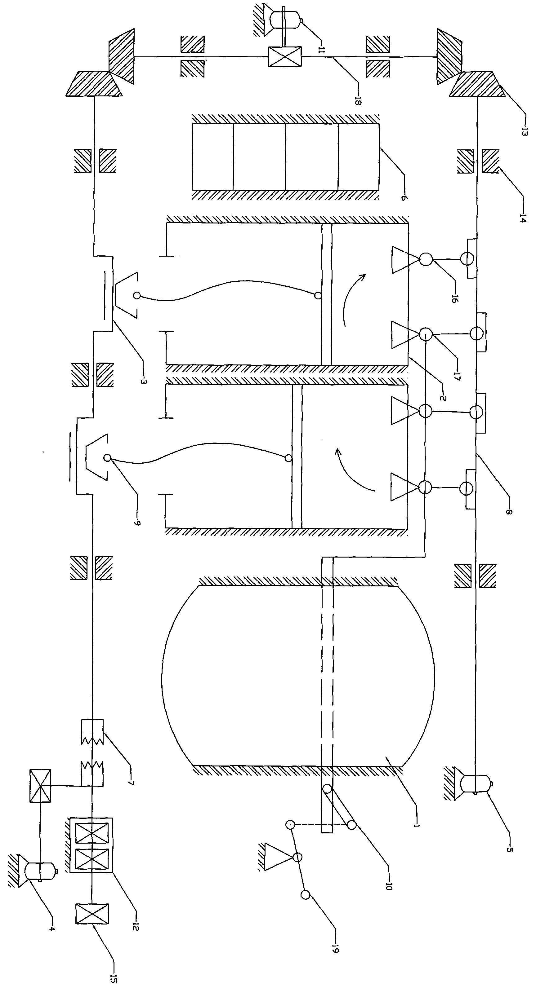
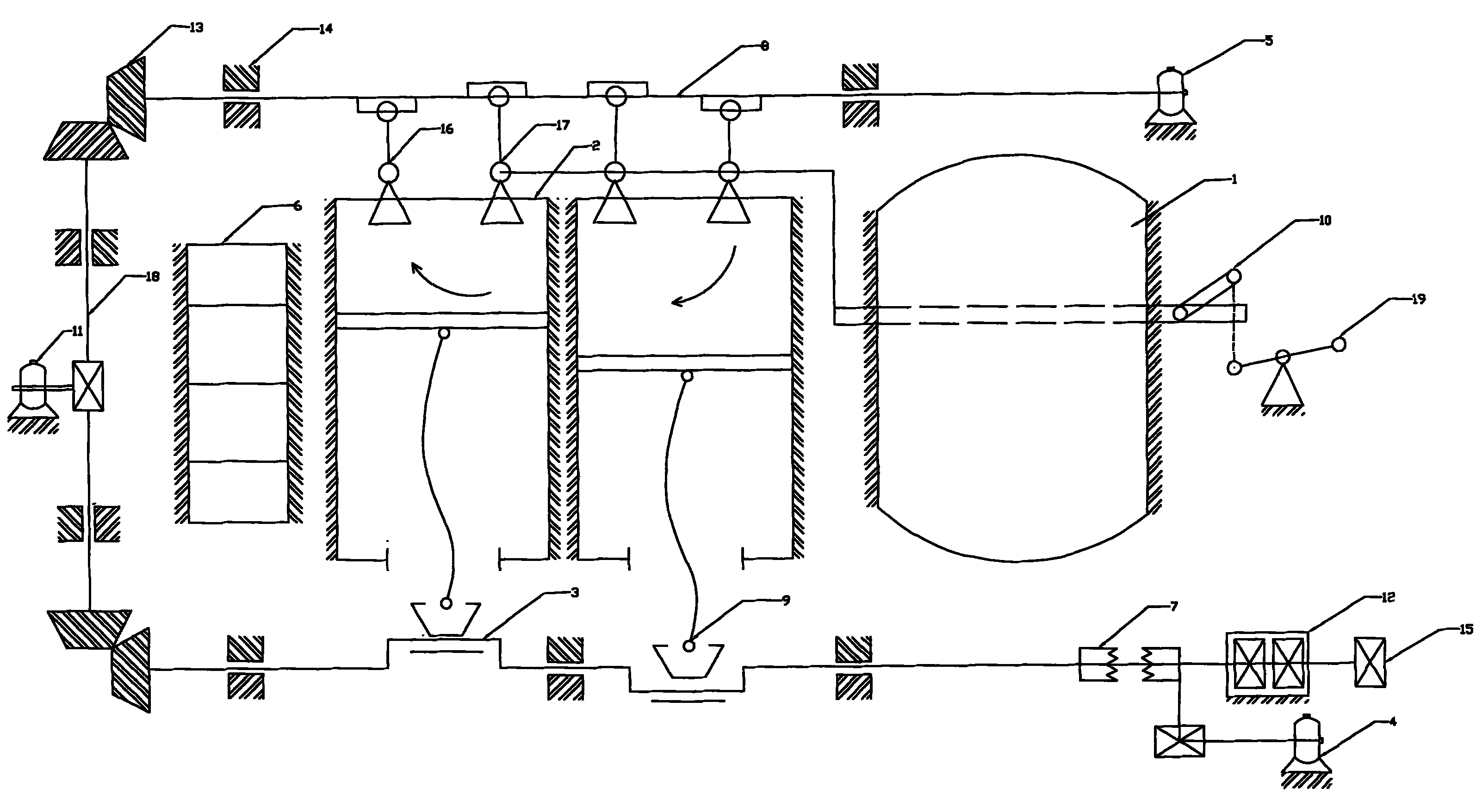
[0010] exist figure 1 In this process, when the starter electric motor 4 rotates the crankshaft 3 through the clutch 7, the piston in the compression cylinder 2 is reciprocated through the connecting rod 9, and at this time, the cam of the camshaft 8 is opened to the compression cylinder 2 for intake air at regular intervals through the transmission shaft 18. Valve 17 and exhaust valve 16, when the control handle 19 makes the rotary valve 10 control the air flow into the compression cylinder 2 to push the piston to move, the power is transmitted to the crankshaft through the connecting rod 9, and through the clutch 7, the gearbox 12 outputs different power and The revs make the vehicle move. When the compressed air automobile runs normally, the charger 11 charges the storage battery 6, and the air compressor 5 inflates the compressed gas cylinder 1.


PUM


Abstract

The invention relates to a compressed air automobile capable of saving petroleum and reducing environmental pollution. In the compressed air automobile, compressed air with certain volume and pressure is stored by a compressed air cylinder; and when an electric motor is started to control the air flow by controlling the rotating angle of a rotary valve, a piston in the compressed air cylinder does reciprocating motion to obtain required power to drive the vehicle.

Description

Technical field [0001] The invention relates to an engine device using compressed air as power, and a compressed air vehicle is a compressed air vehicle that transmits energy through the physical action of air. Background technique [0002] At present, the known vehicle engine is powered by fuel oil, which consumes a large amount of oil, and the exhaust gas discharged after combustion has brought serious pollution to the environment, thus bringing great harm to human beings and also to human beings. Energy creates a shortage. Contents of the invention [0003] In order to overcome the harm brought by the traditional fuel petroleum used in the existing automobile engines, the utility model of the present invention provides a compressed air automobile. The compressed air vehicle not only can replace petroleum fuel with compressed air, but also keeps the environment free from pollution. [0004] The technical solution adopted by the present invention to solve its technical ...

Claims


Application Information

Patent Timeline
Patent Type & Authority Applications(China)
IPC IPC(8): B60K3/02F01B17/02F01B23/02
Inventor 孙风举
Owner 孙风举
Learn More