High-temperature steam jetting type oil sand and oil sludge treatment device

A high-temperature steam and treatment device technology, applied in sludge treatment, water/sludge/sewage treatment, pyrolysis treatment of sludge, etc., can solve the problems of high treatment cost, long time, low recycling rate, etc. Tank temperature, easy to control, direct effect of heat

Inactive Publication Date: 2011-08-03
NANGUANG YANSHAN LIGHT STEEL STRUCTURE ENG TANGSHAN
View PDF5 Cites 11 Cited by
  • Summary
  • Abstract
  • Description
  • Claims
  • Application Information

AI Technical Summary

Problems solved by technology

[0003] At present, the treatment methods of oil sludge reported in the literature include biological treatment, freezing and thawing treatment, solvent extraction treatment, coking treatment, etc., which generally have high energy consumption, high treatment cost, secondary environmental pollution, long time, and occupied area. Large, low recycling rate and other problems, the requirements for the composition of the sludge are too high, especially when there are too many impurities and the sludge is solidified and agglomerated, it is basically difficult for the separation device to complete the evaporation of oil and water

Method used


Image

  • High-temperature steam jetting type oil sand and oil sludge treatment device
  • High-temperature steam jetting type oil sand and oil sludge treatment device
  • High-temperature steam jetting type oil sand and oil sludge treatment device

Examples


Embodiment Construction

[0010] The present invention will be described in detail below in conjunction with the accompanying drawings and embodiments.

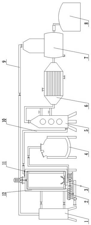
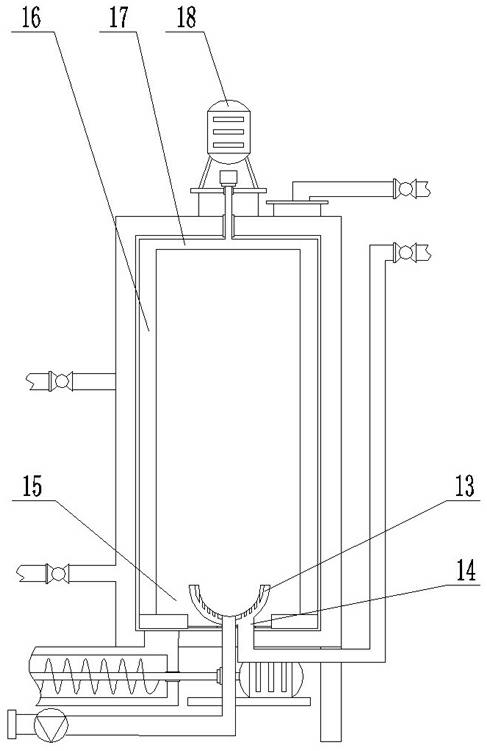
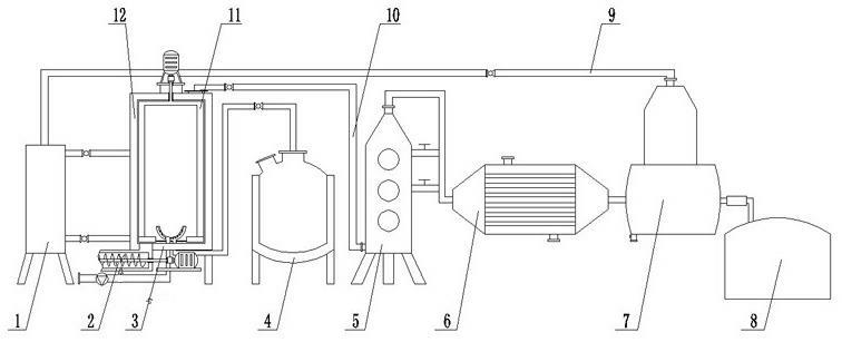
[0011] see figure 1 , figure 2 , the cracking evaporation tank 3 is a vertical tank body, the tank body is provided with a heat exchange interlayer 12, the heat transfer interlayer 12 is built into the heat transfer oil communicated with the heating oil furnace 1, and the lower part of the tank is equipped with an evaporation pan 13, the evaporation There is a spray hole in the center of the disc 13, and the spray hole is connected to the feed pump 19 through the feed nozzle 15, and the high-temperature steam nozzle 14 connected to the superheated steam boiler 4 is evenly arranged on the periphery of the spray hole, and the pyrolysis evaporation tank 3 A rotary scraper 11 is also installed, and an exhaust port is provided on the top of the tank, which is connected to the fractionation tower 5 through a gas pipeline 10, and a spiral slagging device 2...


PUM


Abstract

The invention relates to oil sludge treatment equipment for oil producing regions of oil fields, in particular to a high-temperature steam jetting type oil sand and oil sludge treatment device which comprises a cracking evaporation pot, a fractionating tower, a condenser and an oil and water separating pot, wherein the cracking evaporation pot is a vertical pot body on which a heat exchange sandwich layer is arranged, heat conducting oil communicated with a heating oil furnace is arranged in the sandwich layer, an evaporation disc is arranged at the lower part in the pot, high-temperature steam nozzles connected with an superheated steam boiler are uniformly distributed at the bottom of the evaporation disc, a feeding spray pipe connected with a raw material pump is arranged at the side of the evaporation disc, a rotary scraper is arranged at the upper part of the evaporation disc, an air vent which is connected with the fractionating tower through an air pipeline is arranged at the top of the pot, and a spiral slag discharging device is arranged at the bottom of the pot. The high-temperature steam jetting type oil sand and oil sludge treatment device enables oil sludge and high-temperature steam to fully contact and collide with each other and has large treatment capacity; the cracking evaporation pot provides an auxiliary heating function for raw materials to be beneficial for the materials to effectively absorb heat to evaporate oil water; and the cracking evaporation pot is heated by circulating heat conducting oil so that the high-temperature steam jetting type oil sand and oil sludge treatment device has safety and is easy to control.

Description

[0001] technical field [0002] The invention relates to equipment for treating sewage sludge in an oil production area of ​​an oil field, in particular to a high-temperature steam injection type oil sand oil sludge treatment device. Background technique [0003] At present, the treatment methods of oil sludge reported in the literature include biological treatment, freezing and thawing treatment, solvent extraction treatment, coking treatment, etc., which generally have high energy consumption, high treatment cost, secondary environmental pollution, long time, and occupied area. Large, low recycling rate and other problems, the requirements for the composition of the sludge are too high, especially when there are too many impurities and the sludge is solidified and agglomerated, it is basically difficult for the separation device to complete the evaporation of oil and water. Contents of the invention [0004] The present invention aims to solve the above-mentioned problem...

Claims


Application Information

Patent Timeline
Patent Type & Authority Applications(China)
IPC IPC(8): C10G1/00C02F11/00C02F11/10
Inventor 高开星
Owner NANGUANG YANSHAN LIGHT STEEL STRUCTURE ENG TANGSHAN
Why Eureka
Try Eureka