Auxiliary gas control system for double-fluid ejector

A technology of auxiliary gas and control system, applied in the direction of liquid injection device, injection device, etc., can solve the problems of nozzle tailing, wire drawing, inability to realize precise distribution of glue liquid, etc., and achieve the effect of convenient operation and easy maintenance.

Inactive Publication Date: 2011-08-17
SHANGHAI UNIV
View PDF4 Cites 2 Cited by
  • Summary
  • Abstract
  • Description
  • Claims
  • Application Information

AI Technical Summary

Problems solved by technology

The two-fluid jet dispensing method is to mix the gas and the glue in the mixing chamber, use the flow characteristics of the fluid itself, adjust the process parameters until the slug flow is formed, and the gas will accurately distribute the glue. In this method, the pressure and flow rate of the gas should be moderate. If the pressure and flow rate are too high, the droplets will be atomized, and if the pressure and flow rate are too small, tailing and wire drawing will occur at the outlet of the nozzle, and the precise glue solution cannot be achieved. Therefore, precise control of gas pressure and flow is one of the key points of two-fluid jet dispensing

Method used


Image

  • Auxiliary gas control system for double-fluid ejector
  • Auxiliary gas control system for double-fluid ejector
  • Auxiliary gas control system for double-fluid ejector

Examples


Embodiment 1

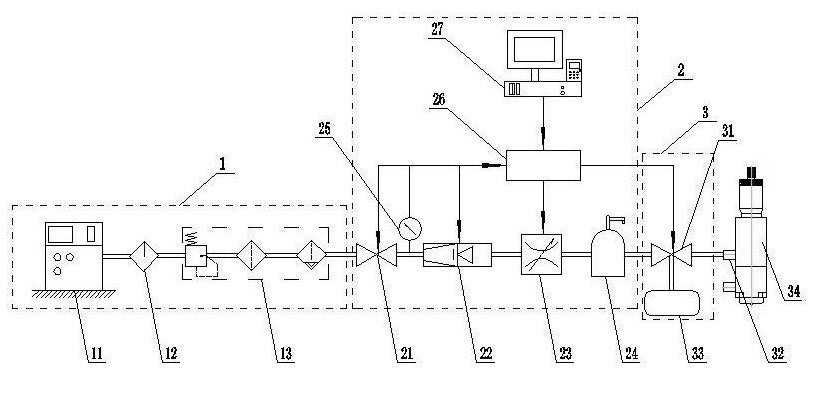
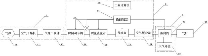
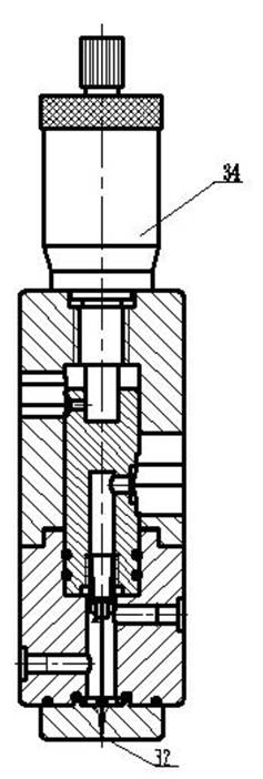
[0026] refer to figure 1 , figure 2 and image 3 , an auxiliary gas control system for a dual-fluid injector, including a gas source device (1), a gas pressure-flow adjustment unit (2), a gas reversing unit (3) and a dual-fluid injector (34), The gas source device (1), gas pressure-flow adjustment unit (2), gas reversing unit (3) and dual-fluid injector (34) are sequentially connected through a gas pipe, and the outlet of the gas reversing unit (3) is connected through a gas pipe The gas needle (32) of the dual-fluid injector (34) realizes the gas supply of the dual-fluid injector (34).

Embodiment 2

[0028] refer to figure 1 and 2 , this embodiment is basically the same as Embodiment 1, the special feature is that the gas source device (1) provides a pure and dry gas source for the system, ensuring the existence of the working medium - gas; the gas source device ( 1) The structure is: a compressed air source (11) is sequentially connected to an air dryer (12) and an air source triple unit (13) through an air pipe, and the air source triple unit (13) is composed of a filter, a lubricator And pressure reducing valve consists of three parts.

Embodiment 3

[0030] refer to figure 1 and 2 , this embodiment is basically the same as Embodiment 1, in particular that the gas pressure-flow adjustment unit (2) provides the downstream equipment with the required flow and pressure of compressed gas to meet the requirements of the experimental process parameters; the gas pressure - The structure of the flow regulating unit (2) is: a proportional regulating valve (21) is sequentially connected to a mass flow meter (22) through the gas pipe, wherein the proportional regulating valve (21), the mass flow meter (22) and the throttle valve (23 ) all have signal ports, and are connected with the signal ports of the microcontroller (26), the microcontroller (26) is connected with the industrial computer (27), and the parameters are set through the industrial computer (27), and the proportional regulating valve ( The outlet of 21) is provided with a pressure sensor (25), and its signal port is connected with the microcontroller (26).


PUM


Abstract

The invention relates to an auxiliary gas control system for a double-fluid ejector, which comprises a gas source device, a gas pressure-flow adjustment unit, a gas reversing unit and the double-fluid ejector, wherein the gas source device, the gas pressure-flow adjustment unit, the gas reversing unit and the double-fluid ejector are orderly connected through a gas pipe; and an outlet of the gas reversing unit is connected with a gas needle of the double-fluid ejector through a gas pipe so as to realize the gas supply of the double-fluid ejector. Through a microcontroller in the gas pressure-flow adjustment unit, a proportion control valve and a mass flow meter are controlled to adjust the pressure and the flow of the gas so that the technological parameter requirements are satisfied; and through the microcontroller, the action of the gas reversing valve is controlled so that the pulsation and continuous gas supply are realized and different technological requirements are satisfied. The auxiliary gas control system for the double-fluid ejector is suitable for the spot gluing technologies such as time-pressure type spot gluing, double-fluid ejection spot gluing, mechanical ejection spot gluing and the like.

Description

technical field [0001] The present invention designs a gas control system, and more particularly relates to an auxiliary gas control system for a dual-fluid injector, the gas control system being a sub-system of a dual-fluid injector injection system. Background technique [0002] Electronic packaging technology is an important part of today's semiconductor manufacturing industry. Glue distribution technology is one of the key technologies in electronic packaging. It is widely used in chip mounting, chip wrapping, thermal silica filling, chip and substrate interconnection, etc. . At present, in the field of fluid dispensing, the driving methods of glue liquid in the most widely used dispensing technology mainly include mechanical needle drive and compressed gas drive, and the corresponding technologies include non-contact jet dispensing, time-pressure dispensing and Two-fluid jet dispensing. [0003] When the non-contact jet dispensing works, the compressed gas is used to ...

Claims


Application Information

Patent Timeline
IPC IPC(8): B05B7/12B05B15/00
Inventor 王志亮张金松彭鹏张建华
Owner SHANGHAI UNIV
Why Eureka
Try Eureka