Submerged chain conveyor

A slag scraper and slag rake technology, which is applied in the field of slag scrapers, can solve the problems of low safety, damage to workers' health, and low work efficiency, and achieve the effects of overcoming high labor intensity, improving production efficiency, and avoiding lead poisoning

Inactive Publication Date: 2011-08-17
HUNAN JIANG YE MECHANICAL & ELECTRICAL TECH CO LTD
View PDF0 Cites 15 Cited by
  • Summary
  • Abstract
  • Description
  • Claims
  • Application Information

AI Technical Summary

Problems solved by technology

Using this method of operation, the labor intensity of slag removal by workers in a high-temperature environment is high, the work efficiency is low, the safety is low, and the slag removal is not clean and thorough. On the one hand, it affects the automatic mass production of the lead-antimony alloy ingot casting unit. The quality of lead ingots is difficult to guarantee. At the same time, because the volatile gas produced by liquid lead or lead-antimony alloy is poisonous, slag mining workers inhale this poisonous gas into their bodies, resulting in lead poisoning, which seriously damages the health of workers. Therefore, those who are willing to engage in this work Rarely, in order to ensure the health of the workers, the workers engaged in this work must be replaced frequently, which increases the labor cost and reduces the work efficiency of the lead-antimony alloy ingot casting unit
The manual slag removal and the automatic production of the lead-antimony alloy ingot casting unit are obviously inconsistent

Method used


Image

  • Submerged chain conveyor
  • Submerged chain conveyor
  • Submerged chain conveyor

Examples


Embodiment Construction

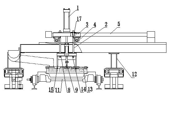
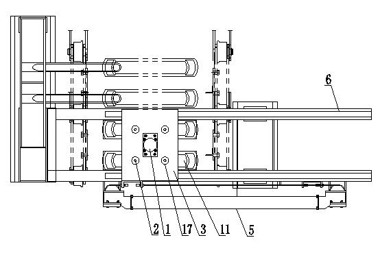
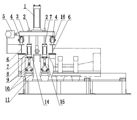
[0018] see Figure 1 to Figure 5 , a kind of slag removing machine, it comprises main cylinder 1, and main cylinder 1 is fixed on platform 3, and platform 3 is provided with several guide sleeves 17, and the bottom of platform 3 is provided with several roller supports 16, and roller supports 16 are installed The roller 4 is movably connected with the two guide rails 6, one side of the platform 3 is connected with the rodless cylinder 5, and the rodless cylinder 5 is fixed at both ends of the guide rail 6; the piston rod hinged bracket 8 of the main cylinder 1 is provided with two A flat plate 14, the lifting cylinder 7 is respectively fixed on the two flat plates 14, the piston rod of the lifting cylinder 7 is coaxially hinged with two connecting rods 9, and each connecting rod 9 is hinged with the hinged arm 20 of the slag rake 10 through the pin shaft 13, and the pin The shaft 13 is movably connected with the two support plates 15 of the bracket 8, and the two slag rakes 10...


PUM


Abstract

The invention discloses a submerged chain conveyor which comprises a main cylinder, wherein the main cylinder is fixed on a platform which is provided with a plurality of guide sleeves, the bottom of the platform is provided with a plurality of idler wheel supports, idler wheels are arranged on the idler wheel supports and movably connected with two guide rails, one side of the platform is connected with a rodless cylinder, the rodless cylinder is fixed at two ends of the guide rails; a piston rod of the main cylinder is hinged with a support frame, the support frame is provided with two flat plates which are respectively used for mixing a lifting cylinder, a piston rod of the lifting cylinder is coaxially hinged with two connecting rods, each connecting rod is hinged with a hinge arm of a slag rake through a pin roll, the pin roll is movably connected with two supporting plates of the support frame; and the two flat plates of the support frame are fixedly provided with a plurality of guide columns, and the guide columns are movably connected with the guide sleeves on the platform. The invention overcomes the defects of large labor intensity and low working efficiency when workers drag for the slag under a high-temperature environment, difficulty in ensuring product quality, low safety and easiness in generating lead poisoning in the prior art, and is suitable for being matched with a lead alloy ingot casting unit or similar equipment for use.

Description

technical field [0001] The invention relates to a production line for producing lead ingots, in particular to a slag removing machine for casting lead ingots. Background technique [0002] Lead-antimony alloy ingot casting unit (patent application number 2011200308279) when casting ingots, liquid lead or lead-antimony alloy is injected into the mold and contacts with air to form lead oxide. The removal of lead oxide is related to the quality of lead ingots, so it needs to be removed The lead oxide slag that floats on the surface of liquid lead or lead-antimony alloy relies on manual slag removal, and the slag is raked out of the mold with a rake. Using this method of operation, the labor intensity of slag removal by workers in a high-temperature environment is high, the work efficiency is low, the safety is low, and the slag removal is not clean and thorough. On the one hand, it affects the automatic mass production of the lead-antimony alloy ingot casting unit. The quality...

Claims


Application Information

Patent Timeline
Patent Type & Authority Applications(China)
IPC IPC(8): B22D9/00B22D43/00
Inventor 王振云唐伏祥张国山
Owner HUNAN JIANG YE MECHANICAL & ELECTRICAL TECH CO LTD
Why Eureka
Try Eureka