Process for treating oil field produced water
A technology for treatment process and produced water, applied in water/sewage multi-stage treatment, water/sludge/sewage treatment, mechanical oscillation water/sewage treatment, etc. And equipment corrosion and other problems, to achieve the effect of superior corrosion resistance, reduced processing costs, and low power costs
- Summary
- Abstract
- Description
- Claims
- Application Information
AI Technical Summary
Problems solved by technology
Method used
Image
Examples
Embodiment 1
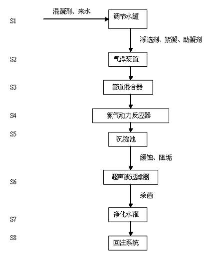
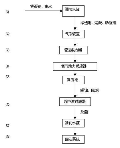
[0031] Such as figure 1 As shown, an oilfield produced water treatment process involves regulating water tanks, air flotation devices, pipeline mixers, nitrogen dynamic reactors, sedimentation tanks and ultrasonic filters. The oilfield produced water treatment process has the following steps:
[0032] In step 1, add coagulant and produced water from the oilfield into the regulating water tank for preliminary adjustment and mixing. The coagulant is commonly used in produced water treatment and can be selected according to needs, and no special requirements are made here.
[0033] In step 2, the regulated oilfield produced water, flotation agent, flocculation and coagulation aid in step 1 are introduced into the air flotation device. The ones commonly used in water treatment can be selected according to needs, and there are no special requirements here. The produced water in the oilfield passes through the high-efficiency dissolved air flotation deoiling process, and the primary...
Embodiment 2
[0043] Such as figure 1 As shown, the process of this embodiment is the same as that of Embodiment 1, except that a new type of nitrogen power reactor is used.
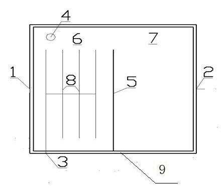
[0044] Such as figure 2 As shown, the nitrogen dynamic reactor at least includes a reactor cavity 9, a nitrogen pipeline 8 and a partition 5; the structure of the reactor cavity 9 is a cuboid, and the middle of the reactor cavity 9 is fixedly connected with a partition 5, a partition 5 The reactor cavity 9 is divided into a front cavity 6 and a rear cavity 7 by adopting a "semi-closed type". Nitrogen gas inlet 3 is arranged on the left side of the front end of the front cavity 6, and the nitrogen gas release port 4 is arranged on the right side of the upper end surface of the front cavity 6, and the nitrogen gas inlet 3 and the nitrogen gas release port 4 are connected through the nitrogen pipeline 8; the nitrogen pipeline 8 is composed of four horizontal pipelines and one vertical pipeline, and adopts a "Feng"-sha...
PUM
 Abstract
Description
Claims
Application Information
 - R&D
- Intellectual Property
- Life Sciences
- Materials
- Tech Scout
- Unparalleled Data Quality
- Higher Quality Content
- 60% Fewer Hallucinations
Browse by: Latest US Patents, China's latest patents, Technical Efficacy Thesaurus, Application Domain, Technology Topic, Popular Technical Reports.
© 2025 PatSnap. All rights reserved.Legal|Privacy policy|Modern Slavery Act Transparency Statement|Sitemap|About US| Contact US: help@patsnap.com


