
Potential difference circulating bioreactor

A bioreactor, circulating technology, applied in bioreactor/fermenter combination, specific-purpose bioreactor/fermenter, biochemical instruments, etc. Advanced problems, to achieve good mixed ventilation effect, enhance ventilation effect, and increase the effect of exchange area

Inactive Publication Date: 2011-08-17
ZHENGZHOU VIRIGE BIOTECH
View PDF4 Cites 4 Cited by
  • Summary
  • Abstract
  • Description
  • Claims
  • Application Information

AI Technical Summary

Problems solved by technology

Its main disadvantage is that the product cannot be cultured at high density for adherent cells. According to reports, it is at least 10 to 100 times lower than that of static perfusion culture.
Secondly, different types of WAVE culture bags need to use matching shakers. Small bags can use large shakers, and large bags can’t use small shakers. It is necessary to purchase a series of expensive equipment
In addition, the WAVE shaking bag is a plastic soft bag, coupled with a series of connected pipes, the operation is more complicated
The AMP rapid flow reactor has the advantages of high dissolved oxygen, low shear force and no cross-contamination of disposable rapid flow reaction bags, but it can only be used for static culture of large-scale adherent cells, not for suspension of non-adherent cells Culture, because the circulation of the medium generated by the peristaltic pump repeatedly squeezes the cells in suspension culture
The equipment is also more expensive and more complicated to operate

Method used


Image

  • Potential difference circulating bioreactor
  • Potential difference circulating bioreactor
  • Potential difference circulating bioreactor

Examples


Embodiment Construction

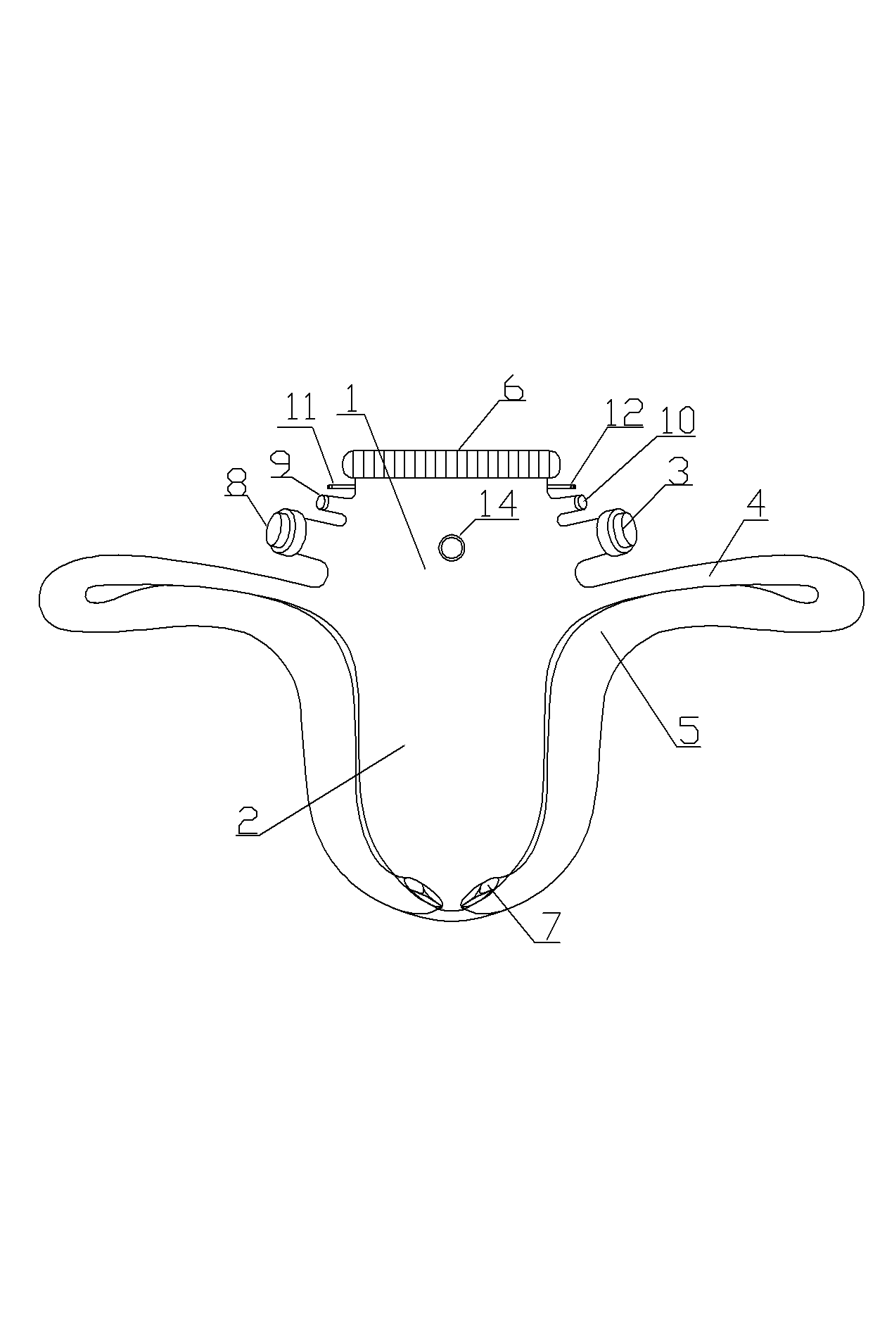
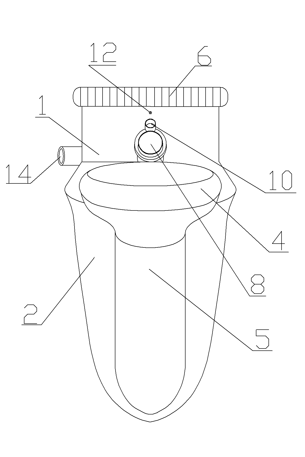
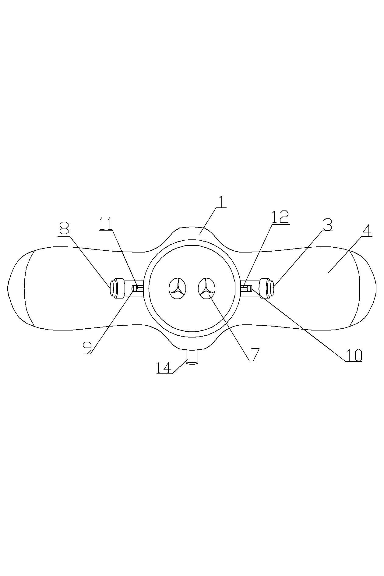
[0031] A kind of embodiment 1 of potential difference circulation type bioreactor, in Figure 1~7 Among them, the reactor includes a container body, and the inner cavity of the container body is divided into upper and lower parts, the upper part is a gas chamber 1, and the lower part is a liquid chamber 2. The side wall of the container body has two side wing channel structures 4 extending to both sides. The side wing channel structure 4 is located at the adjoining place of the air holding chamber and the liquid containing room. The side wing channel structure 4 has two ports inside and outside. The inner port of the channel structure 4 communicates with the inner cavity of the container body, the outer port of the flank channel structure 4 communicates with the upper port of the circulation pipe 5, and the upper section of the circulation pipe 5 is arranged close to the bottom of the flank channel structure 4, and the circulation pipe 5 The upper end of the upper end extends ...


PUM


Abstract

The invention relates to a potential difference circulating bioreactor which comprises a container, wherein the inner cavity of the container is divided into an upper gas-containing chamber and a lower liquid-containing chamber; a lateral wing channel structure extending towards a lateral wing is arranged at the joint between the gas-containing chamber and the liquid-containing chamber on the side wall of the container; the inner port of the lateral wing channel structure is communicated with the inner cavity of the container; the outer port of the lateral wing channel structure is provided with a circulating pipe in a communication mode; the lower port of the circulating pipe is communicated with the bottom of the inner cavity of the container; and a one-way venting valve is arranged in the pipeline of the circulating pipe or at the lower port of the circulating pipe. When the bioreactor is driven to transversely swing or the lateral wing channel structure is driven to vertically swing by certain power, an altitude difference can be formed between the liquid level in the upper section of the circulating pipe and the liquid level in the liquid-containing chamber under the action of the one-way venting valve, so that the potential difference can drive the culture solution to flow to the bottom of the container through the lower circulating pipeline and realize the circulation of the culture solution between the liquid-containing chamber and the circulating pipeline, thereby finishing sufficient gas-liquid exchange and efficient culture solution mixing.

Description

technical field [0001] The invention relates to a potential difference circulation bioreactor which uses gravity potential energy to promote the circulation of culture fluid. The bioreactor is mainly used for animal cell culture and the production of biotechnology products using animal cells, and can also be used for insect cells and plant cells and the cultivation of microorganisms and the production of biotechnological products. Background technique [0002] The use of cultured animal cells (including human cells) for life science research, cell transplantation to treat clinical diseases and production of biotechnology products (such as proteins, polypeptides, nucleic acids, antibodies, viral vectors and viral vaccines), often Efficient and large-scale animal cell culture is required, so it is necessary to develop and produce animal cell reactors that can meet high-efficiency and large-scale production. The so-called animal bioreactor is a device for large-scale animal ce...

Claims


Application Information

Patent Timeline
Patent Type & Authority Applications(China)
IPC IPC(8): C12M3/00C12M1/00
CPCC12M41/00C12M23/36C12M23/02C12M23/26
Inventor 韩志强李顺灵张明环刘慧涛
Owner ZHENGZHOU VIRIGE BIOTECH
Learn More