Optical-fiber type laser wavemeter

A laser wavelength meter and fiber optic technology, applied in the field of wavelength meters, can solve the problems of increasing the difficulty of optical tuning and alignment, increasing energy loss and device complexity, reducing the accuracy of wavelength calibration, etc., to avoid maintenance and debugging, Improved energy transmission efficiency, high accuracy effects

Active Publication Date: 2011-08-17
南京海莱特激光科技有限公司
View PDF7 Cites 20 Cited by
  • Summary
  • Abstract
  • Description
  • Claims
  • Application Information

AI Technical Summary

Problems solved by technology

This technique requires an additional laser with a known precise wavelength as a reference light source, but the wavelength drift of the wavelength calibration device itself will reduce the accuracy of the wavelength meter
On the other hand, the laser transmission between the optical components of the wavelength meter requires more optical components, which increases the difficulty of optical tuning and alignment; the use of photodiodes to monitor the intensity of laser light passing through the Pt hollow transparent cathode lamp The method to calibrate the absorption wavelength, the disadvantage of this technology is that the fluctuation of laser energy will seriously reduce the accuracy of wavelength calibration; multiple plane mirrors are used in the rough wavelength measurement device to expand and collimate the laser beam, and the multiple reflections increase the energy Loss and device complexity, see prior art [EP0992093]

Method used


Image

  • Optical-fiber type laser wavemeter
  • Optical-fiber type laser wavemeter
  • Optical-fiber type laser wavemeter

Examples


Embodiment Construction

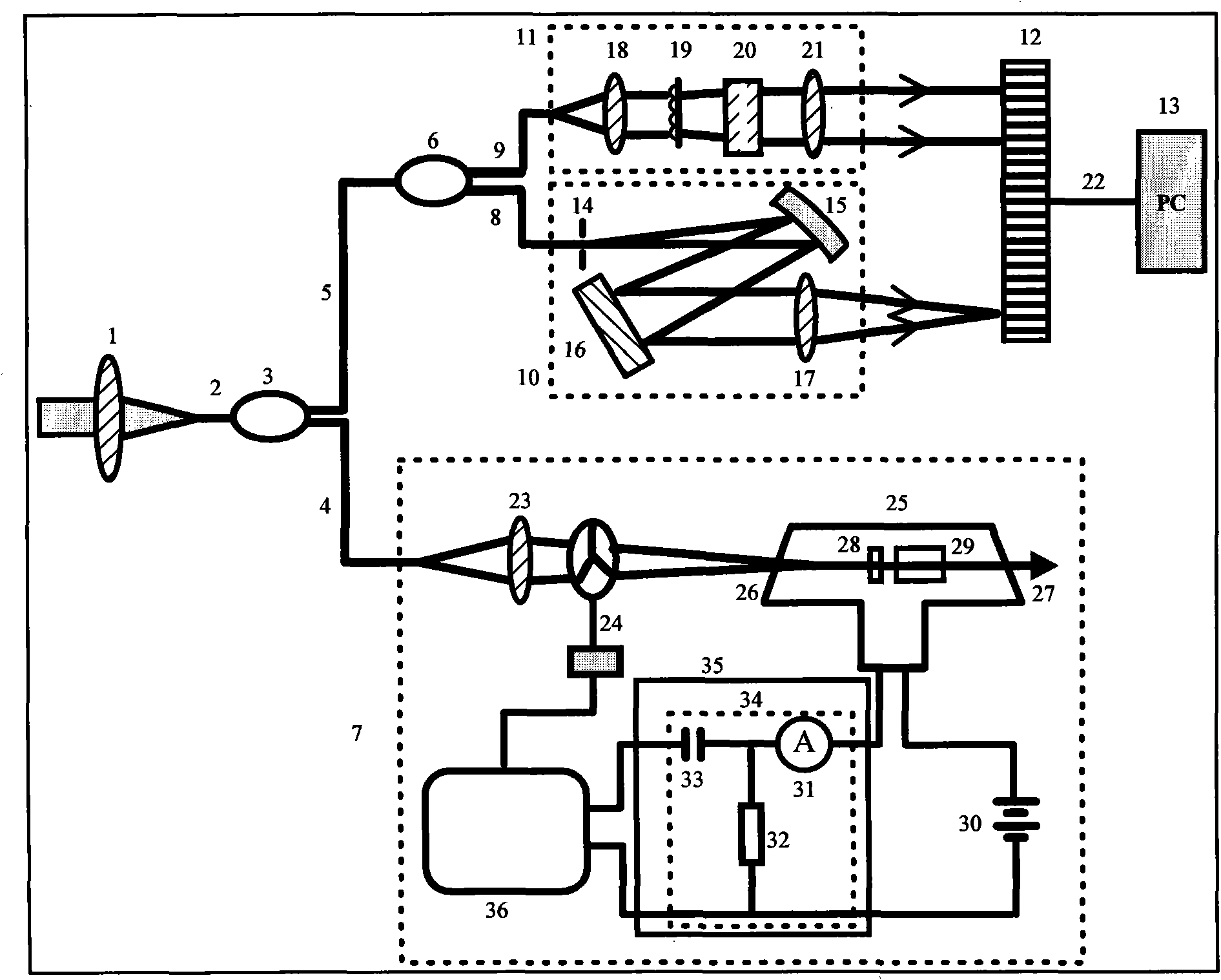
[0034] see figure 1 , figure 1 It is a schematic diagram of the structure of the fiber optic wavelength meter of the present invention. As can be seen from the figure, the optical fiber laser wavelength meter of the present invention consists of a focusing lens 1, a first fused silica optical fiber 2, a second fused silica optical fiber 4, a third fused silica optical fiber 5, a fourth fused silica optical fiber 8, and a fifth fused silica optical fiber 9. The first fiber coupler 3, the second fiber coupler 6, wavelength calibration device 7, grating monochromator 10, wavelength precision measurement device 11, linear CCD 12, signal processor 13 and data line 22, the above-mentioned parts The positional relationship is as follows:

[0035] The laser to be measured is coupled to the first fused silica fiber 2 through the focusing lens 1 and transmitted to the first fiber coupler 3 with a high beam splitting ratio for beam splitting. The stronger beam split by the first fiber co...


PUM


Abstract

The invention provides an optical-fiber type laser wavemeter that consists of a lens, fusing quartz optical fiber, an optical fiber coupler, a wavelength calibrating device, a grating monochromator, a wavelength precise measurement device, a linear CCD (Charge Coupled Device), a signal processor and a data wire. In the invention, the fusing quartz optical fiber is used for guiding light and the optical fiber coupler is used for splitting beam so that the spatial dimension and complexity of the wavemeter can be effectively reduced; and the calibration, coarse measurement and precise measurement of the wavelength are effectively combined so as to realize high-precision real-time measurement on the central wavelength and spectrum bandwidth of the laser. In the invention, the linear width and the central wavelength of the continuous laser and the pulse laser can be measured precisely and conveniently at high speed, and the optical-fiber type laser wavemeter is particularly used for measuring the laser wavelength of an excimer laser.

Description

technical field [0001] The invention relates to a wavelength meter, in particular to a fiber optic laser wavelength meter. Background technique [0002] Excimer lasers are widely used in VLSI lithography due to their short wavelength and weak coherence. As a light source for lithography, laser output is required to have narrow linewidth and high wavelength stability. Factors such as vibration and temperature changes of the laser line width narrowing device can cause the center wavelength of the laser to drift. In order to obtain the center wavelength of the laser and judge the amount of drift between it and the target wavelength, and provide a basis for tuning the center wavelength of the laser, it is necessary to Real-time fast measurement of central wavelength and linewidth. [0003] A common method for measuring laser wavelength is to use a Fesault interferometer, see the prior art [Chinese Patent Publication No. 1077530]. This technique requires an additional laser wi...

Claims


Application Information

Patent Timeline
Patent Type & Authority Applications(China)
IPC IPC(8): G01J9/02
Inventor 袁志军张海波周军楼祺洪董景星魏运荣
Owner 南京海莱特激光科技有限公司
Why Eureka
Try Eureka