Simplified assessment method for defects of welding joint area at piping safety end of pressure vessel of AP1000 nuclear reactor

A technology for pressure vessels and nuclear reactors, applied in nuclear reactor monitoring, reactors, nuclear engineering, etc., can solve the problems of lack of third-generation AP1000 nuclear power equipment or component-specific defects, dissimilar metal joints cannot be accurately processed, evaluation methods, etc.

Active Publication Date: 2011-08-17
EAST CHINA UNIV OF SCI & TECH
View PDF5 Cites 8 Cited by
  • Summary
  • Abstract
  • Description
  • Claims
  • Application Information

AI Technical Summary

Problems solved by technology

In the existing international simplified methods related to the defect assessment of nuclear power equipment, the safety end of the nuclear reactor pressure vessel with a complex geometric structure is generally simplified as a straight pipe. Allowable defect size guidelines, evaluating the safety of defects, these methods do not accurately account for the influence of complex structural geometry on the safe side
Butt welded joints are generally simplified to two materials: the base metal and the weld. According to the different positions of the cracks in the base metal and the weld, only the mechanical performance parameters of the corresponding materials are taken for analysis. For the four materials (two weld

Method used


Image

  • Simplified assessment method for defects of welding joint area at piping safety end of pressure vessel of AP1000 nuclear reactor
  • Simplified assessment method for defects of welding joint area at piping safety end of pressure vessel of AP1000 nuclear reactor
  • Simplified assessment method for defects of welding joint area at piping safety end of pressure vessel of AP1000 nuclear reactor

Examples


Embodiment 1

[0060] (1) Defect characterization:

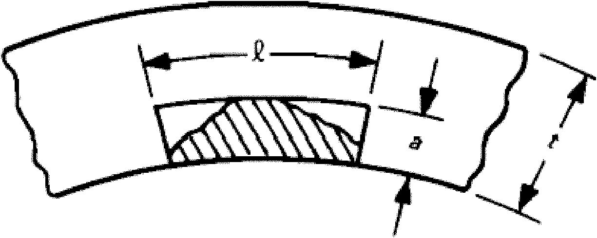
[0061] If the defect on the circumferential inner surface exceeding the standard is detected in the dissimilar metal weld area at the safe end of AP1000 or the size of the defect at the end of the evaluation period is calculated, press figure 1 Characterization determined a defect depth a = 32 mm and a defect length l = 448 mm.

[0062] (2) Determination of stress at the safe end:

[0063] The outer diameter of the pipe at the safe end of the AP1000 nuclear reactor pressure vessel is D=952.5mm, the pipe wall thickness t=82.6mm, and the designed pipe internal pressure p=17MPa, then the primary film stress can be calculated according to formula (1):

[0064] σ m = pD / 4t = 49 MPa.

[0065] As measured by the experiment, the yield strength σ of the nickel-based alloy weld zone material at the safe end at the working temperature of 340°C y =365MPa, tensile strength σ u =635MPa, then the flow stress of the material can be calculated:

[00...


PUM


Abstract

The invention relates to a simplified assessment method for defects of a welding joint area at a piping safety end of a pressure vessel of an AP1000 nuclear reactor. The method comprises the following steps of: characterizing the detected dimension of a circumferential inner surface defect, and determining a defect depth a and a defect length l; calculating primary membrane stress sigma m which is vertical to a defect surface at the position of the circumferential inner surface defect in absence of the defect under an assessment working condition; calculating the relation of primary bending stress sigma b which is vertical to the defect surface at the position of the circumferential inner surface defect in absence of the defect and an extra bending moment M which is borne by the safety end through three-dimensional finite element analysis; determining the primary bending stress sigma b which corresponds to a resultant bending moment Mt according to the resultant bending moment Mt under the assessment working condition; calculating the rheological stress sigma f of a material in the welding joint area, and calculating a stress ratio SR which is equal to (sigma m+ sigma b)/ sigma f; calculating the relation of the stress ratio, a nominal defect length and a nominal permitted defect depth according to a three-dimensional finite element model; and judging whether the defect depth a is less than or equal to the permitted defect depth a or not.

Description

technical field [0001] The invention belongs to the technical field of structural integrity assessment, and in particular relates to a simplified assessment method for the circumferential inner surface defect of the dissimilar metal weld zone at the safety end of the AP1000 third-generation nuclear reactor pressure vessel. It is a simplified evaluation method for evaluating and judging the safety of pre-service and in-service circumferential over-standard defects in the safety end weld area under specified operating conditions, and is applicable to the safety management and control of nuclear power equipment. Background technique [0002] As a clean and efficient energy source, nuclear power is being vigorously developed in our country. Nuclear safety is the lifeline of nuclear power development. Due to its special reaction conditions and technological process in the nuclear power industry, once an accident occurs, it will cause catastrophic consequences. Ensuring the safe...

Claims


Application Information

Patent Timeline
IPC IPC(8): G21C17/003G21C17/01G21C17/017
CPCY02E30/30
Inventor 王国珍刘志伟轩福贞涂善东
Owner EAST CHINA UNIV OF SCI & TECH
Why Eureka
Try Eureka