Crystalline silicon solar battery

A solar cell and crystalline silicon technology, applied in the field of solar cells, can solve problems such as reducing solar cell performance, increasing battery series resistance, and reducing device performance, so as to improve battery performance, increase short-circuit current and open-circuit voltage, and reduce recombination rate. Effect

Inactive Publication Date: 2011-08-17
ZHEJIANG UNIV
View PDF4 Cites 6 Cited by
  • Summary
  • Abstract
  • Description
  • Claims
  • Application Information

AI Technical Summary

Problems solved by technology

Traditionally thermally oxidized SiO 2 Passivation of silicon surfaces is possible, but thermal oxidation of SiO 2 It is difficult to grow on one side, which will affect the front of the battery and reduce the performance of the device
SiN x Thin films can be used to passivate silicon, but when this film is applied to the back passivation, due to the "parasitic effect" (Parasitic Effect), the performance of solar cells will be reduced
It was also studied using Al 2 o 3 The film is passivated on the back, but there are still "parasitic effects"
Moreover, SiO 2 、SiN x 、Al 2 o 3 They are all insulating materials and cannot conduct electricity, which will increase the series resistance of the battery and limit its passivation

Method used


Image

  • Crystalline silicon solar battery
  • Crystalline silicon solar battery

Examples


Embodiment 1

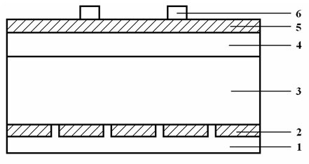
[0023] After the p-type Si base layer 3 is textured, an n-type Si diffusion layer 4 is formed on it by a diffusion method; a transparent ZnO layer co-doped with H and Nb is deposited on the n-type Si diffusion layer 4 by a magnetron sputtering method. The conductive thin film is the front ZnO-based thin film layer 5, and the ZnO transparent conductive thin film co-doped with H and Ga is deposited on the p-type Si substrate layer 3, which is the rear ZnO-based thin film layer 2; the main electrode of Ag is vacuum evaporated respectively by evaporation method Thick wire 6 and Al electrode 1, Ag main electrode thick wire 6 are deposited using mask technology, before Al electrode 1 is deposited, the ZnO-based thin film layer 2 on the back is etched and opened, and Al electrode 1 is formed into a dot electrode. The photoelectric conversion efficiency of the produced crystalline silicon solar cells is 18~21%.

Embodiment 2

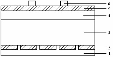
[0025] After the p-type Si base layer 3 is textured, an n-type Si diffusion layer 4 is formed on it by a diffusion method; using a CVD method, on both sides of the n-type Si diffusion layer 4 and the p-type Si base layer 3, simultaneously deposit H The ZnO transparent conductive film co-doped with Al forms the front ZnO-based thin film layer 5 and the back ZnO-based thin film layer 2, and the back ZnO-based thin film layer 2 is deposited using mask technology; The main electrode thick wire 6 and the Al electrode 1 and the Ag main electrode thick wire 6 are deposited using mask technology, and the Al electrode 1 forms a linear electrode. The photoelectric conversion efficiency of the produced crystalline silicon solar cells is 18-22%.

Embodiment 3

[0027] After the p-type Si base layer 3 is textured, an n-type Si diffusion layer 4 is formed on it by a diffusion method; using a magnetron sputtering method, on the n-type Si diffusion layer 4 and the p-type Si base layer 3, double-sided Simultaneously deposit the ZnMgO transparent conductive film that H and Ga are co-doped to form the front ZnO-based thin film layer 5 and the back ZnO-based thin film layer 2. The mask plate technology is used when the back ZnO-based thin film layer 2 is deposited; The Ag main electrode thick wire 6 and the Al electrode 1 are evaporated, the Ag main electrode thick wire 6 is deposited using mask technology, and the Al electrode 1 forms a linear electrode. The photoelectric conversion efficiency of the produced crystalline silicon solar cells is 19~23%.


PUM

PropertyMeasurementUnit
thicknessaaaaaaaaaa
thicknessaaaaaaaaaa
transmittivityaaaaaaaaaa

Abstract

The invention discloses a crystalline silicon solar battery. The crystalline silicon solar battery comprises an Al electrode, a back ZnO-based thin film layer, a p-type Si substrate layer, an n-type Si diffusion layer, a front ZnO-based thin film layer and an Ag main electrode thick line in turn. The crystalline silicon solar battery has the advantages of high photoelectric conversion efficiency, high stability, simple process, and low production cost, and can improve the performance and prolong the service life of the crystalline silicon solar battery.

Description

technical field [0001] The invention relates to a solar cell, in particular to a crystalline silicon solar cell. Background technique [0002] Solar energy is an inexhaustible green renewable energy source. Solar power generation is a new energy industry supported by all countries in the world. In recent years, the world's photovoltaic power generation industry has grown at a rate of 30%. In 2010, the global solar cell production capacity reached 12GW, of which crystalline silicon solar cells exceeded 9GW, accounting for more than three quarters of the entire market. At present, the photoelectric conversion efficiency of crystalline silicon solar cells is about 17% on average, and the cost of photovoltaic power generation is 1.3-2.0 yuan / kWh. Compared with the price of civilian electricity, the cost is still too high and it is difficult to connect to the grid for power generation. To further reduce the cost of solar cell power generation, the most effective way is to impro...

Claims


Application Information

Patent Timeline
Patent Type & Authority Applications(China)
IPC IPC(8): H01L31/0216H01L31/0224
Inventor 吕建国叶志镇黄继杰
Owner ZHEJIANG UNIV
Why Eureka
Try Eureka