Strong-strength broadband antenna for flying carrier and preparation process thereof

A broadband antenna, high-intensity technology, applied in the direction of the antenna suitable for movable objects, the structure of the radiating element, the cover of the radiating element, etc., can solve the problem of low structural strength, narrow bandwidth, and the antenna radiation pattern cannot meet the actual use requirements. And other issues

Inactive Publication Date: 2013-10-30
CETC YANGZHOU BAOJUN ELECTRONICS
View PDF6 Cites 0 Cited by
  • Summary
  • Abstract
  • Description
  • Claims
  • Application Information

AI Technical Summary

Problems solved by technology

[0003]The traditional flying carrier antenna uses a single monopole antenna, which only has a cylindrical or rectangular columnar structure plus a plane reflection ground, and the antenna's The radome is not molded, and the disadvantages of the antenna are low structural strength, large size, and narrow bandwidth
Of course, the antenna with microstrip structure can also be used, which is more conducive to conformality, but the radiation pattern of this type of antenna often cannot meet the actual use requirements

Method used


Image

  • Strong-strength broadband antenna for flying carrier and preparation process thereof
  • Strong-strength broadband antenna for flying carrier and preparation process thereof
  • Strong-strength broadband antenna for flying carrier and preparation process thereof

Examples


Embodiment 1

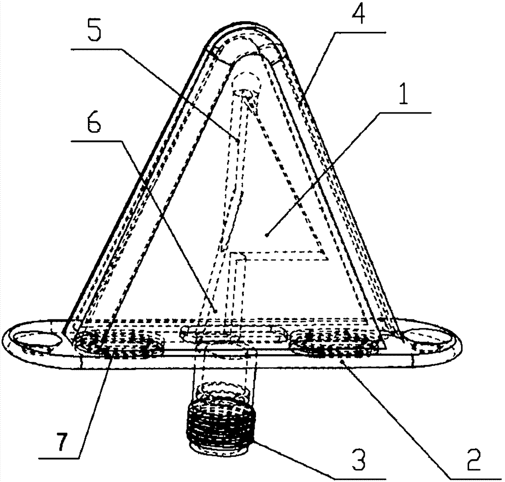
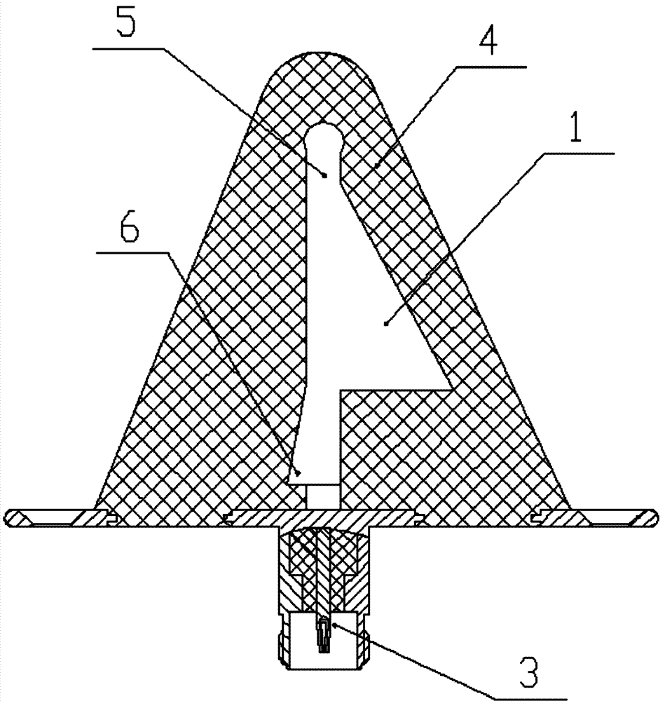
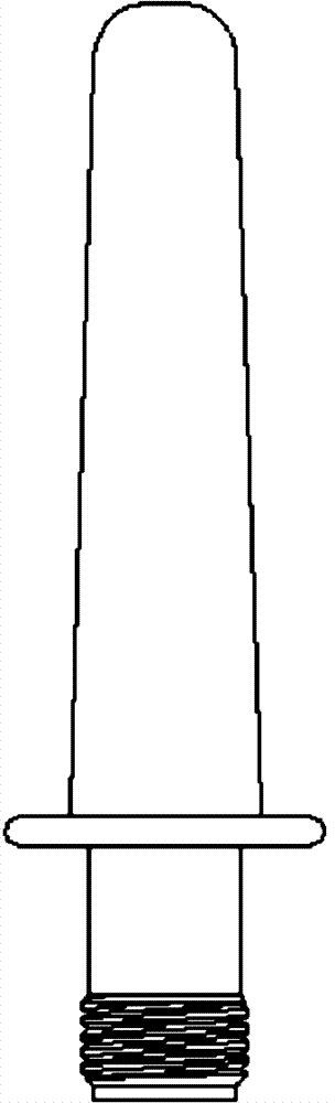
[0022] A high-strength broadband antenna for a flight carrier, comprising: a metal reflection ground 2 with a middle hole, and a solid radome connected to the metal reflection ground 2 4 , in a solid radome 4 A radiation oscillator is embedded inside, and the radiation oscillator includes a cylindrical monopole metal oscillator 5 , in a cylindrical monopole metal oscillator 5 There is at least 1 side wing, the cylindrical monopole metal vibrator 5 Self-solid radome 4 Extend and pass through the middle hole on the metal reflection ground 2 until the solid radome 4 external, cylindrical unipolar metal vibrator 5 of exposure to solid radome 4 The external part is connected with N head. In this embodiment, the shape of the side wings is a triangle, a rectangle or a trapezoid; a connection hole 7 is provided on the metal reflection ground 2 and the connection hole 7 is located around the middle hole, and the solid radome 4 With connection tabs, solid radome 4 The connectio...

Embodiment 2

[0024] A preparation process of a high-strength broadband antenna for a flight carrier, the specific steps are as follows: firstly, a mold is opened according to the structure of the solid radome and the antenna reflection ground, the antenna reflection ground and the antenna radiation vibrator are placed in the mold, and at the same time, the small hole is passed through the mold Inject a fluid solid radome dielectric material (that is, a dielectric material in a molten state), and after the material fills the entire mold, it is cooled, and finally the mold is removed to obtain an integrated antenna.

[0025] Participate in the detailed content of a preferred embodiment of the present invention below, embodiment is described in conjunction with accompanying drawing. Wherever possible, the same reference numbers will be used throughout the drawings and descriptions to refer to the same or like parts. This embodiment is a kind of antenna that is used in civil aviation etc., and...


PUM


Abstract

The invention discloses a strong-strength broadband antenna for a flying carrier, which comprises a metallic reflective ground with a central hole. A solid antenna housing is connected to the metallic reflective ground. A radiation oscillator is embedded in the solid antenna housing, and comprises a columnar monopole metallic oscillator on which at least one side wing is arranged. The columnar monopole metallic oscillator is extended from the interior of the solid antenna housing, and passes through the central hole on the metallic reflective ground until reaching the outside of the solid antenna housing. The part, exposed outside the solid antenna housing, of the columnar monopole metallic oscillator is connected with an N terminal. The preparation process of the strong-strength broadband antenna for the flying carrier comprises the following specific steps of: reserving a mould according to the solid antenna housing and the reflective ground structure of the antenna, arranging the reflective ground and radiation oscillator of the antenna in the mould, simultaneously injecting a fluidic solid antenna housing dielectric material into the mould through a small hole, performing cooling after the whole mould is filled with the material, and finally removing the mould to obtain the integrated antenna.

Description

technical field [0001] The invention relates to a high-strength broadband antenna suitable for flight carriers. Its typical working frequency band is an ultra-high frequency band, that is, a UHF frequency band. It has the advantages of high structural strength, wide operating frequency band, small size, and low cost. It is mainly used in identification systems and communication systems equipped on various flight carriers. Background technique [0002] At present, no matter on a civil aviation aircraft, it is generally equipped with various communication systems. Of course, these systems need to have antennas to work. These antennas are generally installed on the surface of the aircraft skin. Of course, the missile also has a communication control system, and it also needs to be equipped with an antenna to work. For this type of high-speed flight carrier, there are similar requirements for the antenna, that is, the antenna requires good structural strength, high and low tem...

Claims


Application Information

Patent Timeline
Patent Type & Authority Patents(China)
IPC IPC(8): H01Q1/28H01Q1/36H01Q1/42
Inventor 曹振新汤燕夏继钢经林左金康
Owner CETC YANGZHOU BAOJUN ELECTRONICS
Why Eureka
Try Eureka