Staggered multi-driving direct-current brushless motor

A DC brushless, multi-drive technology, applied in the direction of magnetic circuit rotating parts, magnetic circuit shape/style/structure, electrical components, etc., can solve the problems of large space occupation, poor rotor balance, waste of axial space of the motor, etc. , to achieve the effect of unchanged structural size, improved torque characteristics, and increased manufacturing costs

Active Publication Date: 2013-09-11
湖州佳星电机有限公司
View PDF3 Cites 0 Cited by
  • Summary
  • Abstract
  • Description
  • Claims
  • Application Information

AI Technical Summary

Problems solved by technology

[0004] 1. The polar teeth of the stator are designed to be asymmetrical in size on both sides, so that when the motor is stationary, the stator polar teeth attract the rotor magnetic poles, which will cause the midpoint of the rotor magnetic poles and the stator polar teeth to deviate from the slight phase, thus ensuring The torque of the motor is not zero when the power is turned on to achieve the purpose of starting the motor, and the motor can run continuously by relying on the inertial force during operation; through this design, although the motor can start and run, the torque at start is relatively small, so the load When it is large, it is difficult to start, the zero torque of the motor still exists, and the torque-to-amplitude ratio of the motor has not been improved, so the dead angle still exists when the rotor is locked, the motor is easy to vibrate, the motor is noisy, and the motor is only suitable for small loads. Quality requirements are not high use on occasion
[0005] 2. At present, three-phase motor circuit is the most used solution, but the circuit cost of three-phase brushless DC motor circuit is expensive, and its cost is usually dozens of times that of ordinary motor drive circuit. The circuit is complex and the circuit space is relatively large. In the micro motor, the circuit needs to be plugged in, and its application and promotion are limited;
[0007] Another example is the patent 200810190379.1 brushless DC motor and its drive unit. Those skilled in the industry will find that the basic solution is that all the stators of the motor have the same shape, and the number of stator teeth corresponds to the number of rotor magnetic poles. The stator corresponds to a drive circuit. The stators are simply superimposed in the axial direction but the relative phases in the radial direction are uniformly staggered. Although this patent does not mention that it can effectively solve the dead angle problem of the motor, the solution it provides is essentially It just solves the problem of zero torque of the motor, and the motor runs without dead angle; because it is composed of two or more stators superimposed in the axial direction, and the insulating material and wire wrap of each stator occupy a large proportion of the axial space, so The precious axial space of the motor is wasted. The total axial thickness of all the stator silicon steel sheets accounts for a small proportion to the entire axial space of the rotor, and its load capacity is very small.
As we all know, in the outer rotor DC brushless motor, the higher the height of the motor, the more difficult the precision and molding of its parts, and the worse the balance of the rotor. Therefore, in the case of the same height of the motor, it is necessary to obtain It is impossible for the motor to have the same load capacity. On the contrary, to obtain a higher motor load capacity, the height of the outer rotor in the axial direction must be greatly increased. When the height reaches a certain level, it will inevitably greatly increase the cost of the production process.
In addition, when it is applied to an inner-rotor brushless DC motor, since the utilization rate of the effective length of the magnet in the axial direction is small, and the magnets of the inner-rotor motor are usually expensive magnetic steel or rare earth materials, the cost of wasted magnetic materials relatively large;
[0008] In addition, the patent 200910025738.2 is a segmented rotor shape reluctance motor, which is a three-phase 6 / 4 structure or a four-phase 8 / 6 structure or a three-phase 12 / 8 structure. It is an inner rotor motor, and the number of rotor poles is more than that of the stator pole The number of sexual teeth is small, and it also has many defects such as expensive price and large space occupation

Method used


Image

  • Staggered multi-driving direct-current brushless motor
  • Staggered multi-driving direct-current brushless motor
  • Staggered multi-driving direct-current brushless motor

Examples


Embodiment Construction

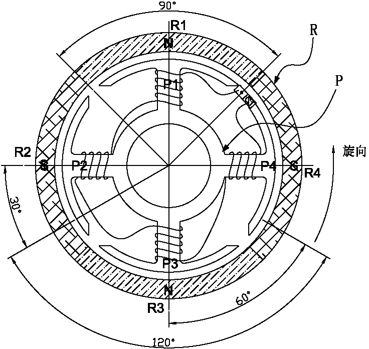
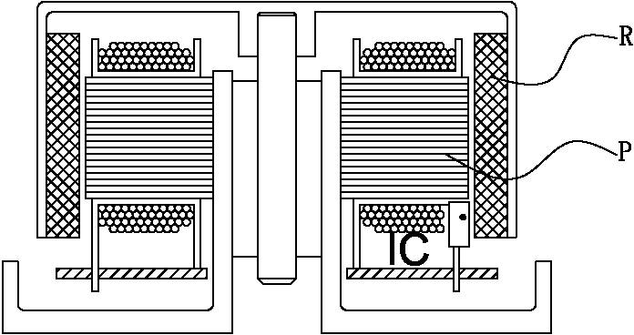
[0059] See Figure 4 to Figure 28 As shown, it shows the specific structure of the preferred embodiment of the present invention. The staggered multi-drive DC brushless motor includes a rotor R, a stator P, and a plurality of inductive phase-interleaved drive circuit ICs. The rotor R surrounds The stator P or is surrounded by the stator P; wherein the rotor R has a plurality of magnetic poles, the stator P has a plurality of polar teeth, and the number of stator polar teeth is less than the number of rotor magnetic poles, and the stator P contains multiple sets of coils, And a group of wire packages bypass the aforementioned one or more stator polarity teeth; the aforementioned multiple drive circuit ICs correspond to multiple groups of wire packages respectively, and the phase time of the polarity switching between the stator polarity teeth is staggered, that is, each or every When the group stator polarity teeth are switched, the remaining stator polarity teeth are in a non-sw...


PUM


Abstract

The invention discloses a staggered multi-driving direct-current brushless motor. The motor comprises a rotor, a stator and a plurality of driving circuits with staggered induction phases, wherein the rotor encircles the stator or is encircled by the stator, and is provided with a plurality of magnetic poles; the stator is provided with a plurality of polar teeth and the number of the polar teeth of the stator is smaller than the number of the magnetic poles of the rotor; the stator comprises multiple groups of coils and one group of coils passes by one or more polar teeth of the stator; the plurality of driving circuits respectively correspond to multiple groups of coils; a phase time alternation for polar switching is performed between the polar teeth of the stator, namely in the switching process of each or each group of the polar teeth of the stator, the rest polar teeth of the stator are in a non-switching working state; torsions which are generated between the polar teeth of the stator and the magnetic poles of the rotor are staggered in phase and overlapped to form torsion of the motor; the torsion of the motor is always more than zero and the minimum torsion of the motor is close to an average torsion; the motor has no running deal angle and the motor has relatively low cost and occupies relatively small space.

Description

Technical field [0001] The invention relates to the technology of the DC brushless motor field, in particular to a dislocation multi-drive DC brushless motor with compact structure, no dead ends in motor operation, good starting performance and greatly reduced cost. Background technique [0002] Such as Figure 1 to Figure 3 As shown, the existing DC brushless motor usually includes a rotor R, a stator P, and a drive circuit IC; the rotor R surrounds the stator P, and the stator P has polar teeth (including P1, P2, P3, P4) The number is equal to the number of rotor R poles (including R1, R2, R3, and R4) and corresponds to the circumference. In this way, when the polarity is switched during the motor operation, since all the midpoints of the stator polarity teeth correspond to the midpoints of the rotor magnetic poles, all the stator polarity teeth must be switched at the same time. At the moment when the stator polarity teeth are switched, The radial force of the motor is the lar...

Claims


Application Information

Patent Timeline
Patent Type & Authority Patents(China)
IPC IPC(8): H02K29/03H02K1/14H02K1/24
Inventor 高林发
Owner 湖州佳星电机有限公司
Why Eureka
Try Eureka