Laser cladding repairing method of piston rod

A technology of laser cladding and repairing methods, which is applied in the coating process and coating of metal materials, can solve problems such as unstable quality, cumbersome process, and low bonding force, so as to reduce scrap rate, save production cost, and reduce spare parts Effects of Cost and Loss

Inactive Publication Date: 2011-08-31
KUNMING UNIV OF SCI & TECH
View PDF8 Cites 18 Cited by
  • Summary
  • Abstract
  • Description
  • Claims
  • Application Information

AI Technical Summary

Problems solved by technology

The above patents are all processes for preparing new piston rods, not repairing old piston rods
In addition, the ceramic coating sprayed by thermal spraying is physically bonded to the substrate, and the bonding fo

Method used


Image

  • Laser cladding repairing method of piston rod
  • Laser cladding repairing method of piston rod
  • Laser cladding repairing method of piston rod

Examples


Embodiment 1

[0031] Example 1: Repair the piston rod of the synchronizer of the steam turbine.

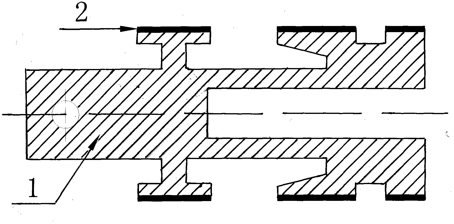
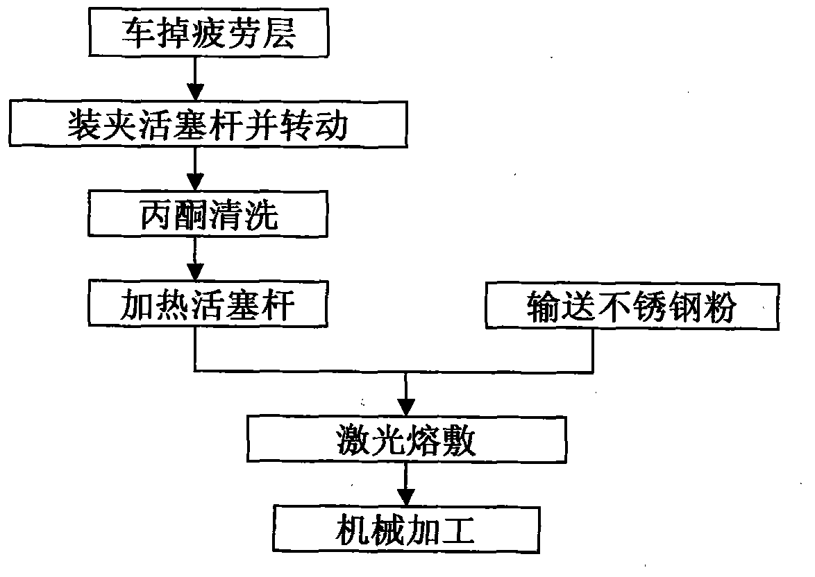
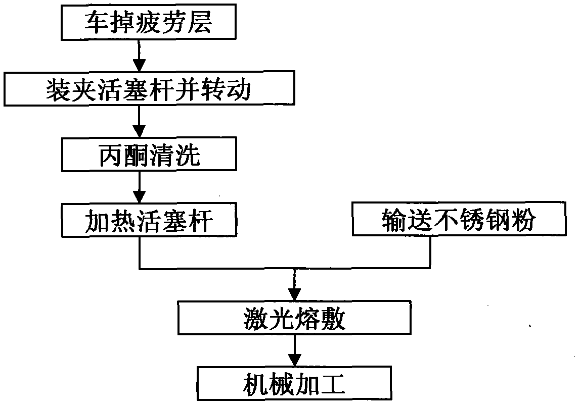
[0032] 1) Use a lathe to remove the 1mm metal fatigue layer of the main body on the working surface of the piston rod (1) of the waste hydraulic cylinder;

[0033] 2) Install the piston rod (1) on the fixture, and rotate the fixture at a linear speed of 600mm / min;

[0034] 3) Pour acetone on the working surface of the piston rod (1) to clean off the oily impurities;

[0035] 4) Heat the piston rod (1) to 60°C with an alcohol blowtorch;

[0036] 5) Conveying martensitic stainless steel powder to the working surface of the piston rod (1);

[0037] 6) Irradiate the martensitic stainless steel powder with a power of 3.5KW and a laser beam with a bandwidth of 3mm to melt it, and deposit a stainless steel surface layer (2) with a thickness of 3mm;

[0038] 7) Remove the piston rod from the fixture, and machine the size and roughness of the piston rod to meet the use size specifications.

[0039] ...

Embodiment 2

[0041] 1. Use a lathe to remove the 2mm metal fatigue layer of the main body on the working surface of the waste hydraulic cylinder liner 1;

[0042] 2. Install the cylinder liner 1 on the fixture, and turn the fixture at a linear speed of 700mm / min;

[0043] 3. Pour acetone on the working surface of the cylinder liner 1 to clean off the oil and impurities;

[0044] 4. Heat the cylinder liner from 1 to 100°C with an alcohol blowtorch;

[0045] 5. Deliver martensitic stainless steel powder to the working surface of cylinder liner 1;

[0046] 6. Irradiate the martensitic stainless steel powder with a laser power of 3.5KW and a bandwidth of 3mm to melt it, and deposit a stainless steel surface layer 2 with a thickness of 7.3mm;

[0047] 7. Remove the cylinder liner from the fixture, and machine the cylinder liner size and roughness to meet the use size specifications.

Embodiment 3

[0049] (1). Use a lathe to remove the 0.5mm body metal fatigue layer on the working surface of the waste hydraulic cylinder liner 1;

[0050] (2). Put the cylinder liner 1 on the fixture, and rotate the fixture at a linear speed of 400mm / min;

[0051] (3.) Pour acetone on the working surface of cylinder liner 1 to clean off oily impurities;

[0052] (4).Heat the cylinder liner from 1 to 40°C with an alcohol blowtorch;

[0053] (5). Conveying martensitic stainless steel powder to the working surface of cylinder liner 1;

[0054] (6). Irradiate the martensitic stainless steel powder with a laser power of 3.5KW and a bandwidth of 3mm to melt it, and deposit a stainless steel surface layer 2 with a thickness of 7.3mm;

[0055] (7). Remove the cylinder liner from the fixture, and machine the cylinder liner size and roughness to meet the use size specifications.


PUM


Abstract

The invention discloses a laser cladding repairing method of a piston rod. The process is realized by the following steps: removing a 0.5-2mm body metal fatigue layer on the working surface of the piston rod by utilizing a lathe; clamping a workpiece; rotating the workpiece in the linear velocity of 400-700mm/min; cleaning grease stains and impurities on the surface by acetone; heating the workpiece to 40-100 DEG C; laser cladding a layer of stainless steel to be used as an antiwear anticorrosion surface layer in 3.5KW power and 3mm bandwidth; and finally mechanically processing the laser cladding layer to achieve the use size specification of the piston rod. The laser cladding repairing method has the advantages of not only realizing the repairing of the old hydrocylinder piston rod, reducing the rejection rate of spare parts and saving the production cost, but also leading the repaired hydrocylinder piston rod to have longer service life and balancer operation performance, and avoiding the use problems that the galling appears on the working surface of the piston rod caused by the reason that the cooling lubricating oil is insufficient or foreign matters enter the cylinder, and hydraulic oil leaks, and the like.

Description

technical field [0001] The invention relates to a hydraulic oil cylinder in the field of mechanical equipment, in particular to a repair process for a hydraulic oil cylinder piston rod. Background technique [0002] The piston rod is the main component of the hydraulic transmission cylinder, and it is also the bearing part in the hydraulic transmission cylinder that converts the pressure of the hydraulic oil into the output of the transmission force. Under the pressure of the hydraulic oil, the piston rod makes frequent reciprocating linear motions in the cylinder. Once foreign matter such as lack of cooling lubricating oil or dust enters the cylinder, it will cause roughening of the piston rod surface, hydraulic oil leakage, and the movement of the cylinder. The conversion efficiency of precision and force is reduced, and even the oil cylinder is scrapped, resulting in the shutdown of the entire mechanical system. [0003] At present, piston rods generally need to go throu...

Claims


Application Information

Patent Timeline
IPC IPC(8): B23P6/00C23C24/10
Inventor 岑启宏黎振华蒋业华周荣范云鹰
Owner KUNMING UNIV OF SCI & TECH
Why Eureka
Try Eureka