Tandem multistage continuous rectification solvent recoverer
A series type and recoverer technology, applied in the direction of fractionation, etc., can solve the problems of large space occupation, large steam loss, low utilization rate, etc., and achieve the effects of reduced floor space, low recovery rate and long service life
- Summary
- Abstract
- Description
- Claims
- Application Information
AI Technical Summary
Problems solved by technology
Method used
Image

Examples
Embodiment 1
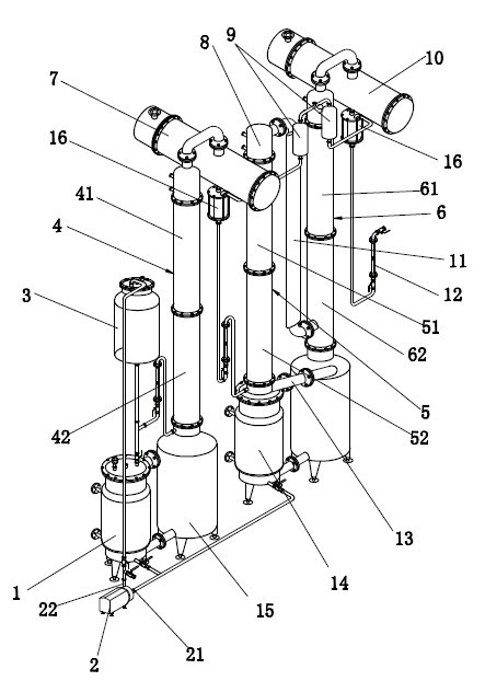
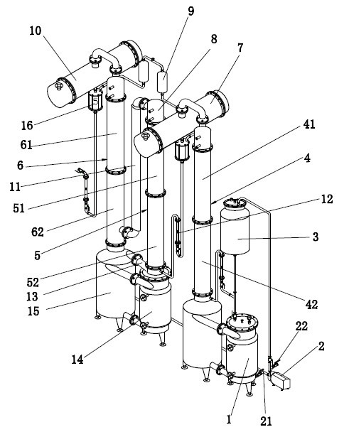
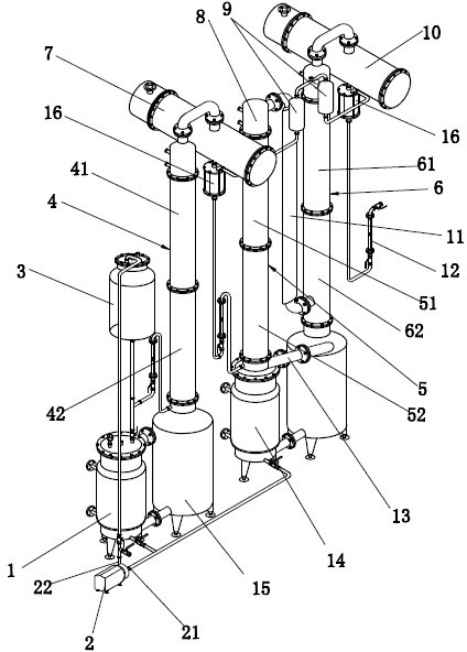
[0026]Take 15% dilute ethanol as an example: the first reboiler 1 and the second reboiler 14 are respectively filled with the dilute concentration solvent, and the steam is turned on for heating. After reaching the boiling point of the solvent, the vaporized liquid produced is The tower evaporates upwards. When the vaporized liquid touches the surface of the precision packing in the tower, the heat exchange process begins on the surface of the packing. At this time, the phenomenon of vapor-liquid separation begins to occur under the action of temperature difference and resistance. The surface of the wall refluxes downward, while the one with light density and low boiling point continues to evaporate upward at a constant temperature, and when it reaches the separator in the top of the tower, reflux separation is carried out, and then part of the light component mixture enters the condenser for condensation. After the vaporized liquid is produced in the cooling process, it flows...
Embodiment 2
[0029] Take 25% dilute ethanol as an example: the first reboiler 1 and the second reboiler 14 are respectively filled with the dilute concentration solvent, and the steam is turned on for heating. After reaching the boiling point of the solvent, the vaporized liquid produced is The tower evaporates upwards. When the vaporized liquid touches the surface of the precision packing in the tower, the heat exchange process begins on the surface of the packing. At this time, the phenomenon of vapor-liquid separation begins to occur under the action of temperature difference and resistance. The surface of the wall refluxes downward, while the one with light density and low boiling point continues to evaporate upward at a constant temperature, and when it reaches the separator in the top of the tower, reflux separation is carried out, and then part of the light component mixture enters the condenser for condensation. After the vaporized liquid is produced in the cooling process, it flow...
Embodiment 3
[0032] Take 35% dilute ethanol as an example: the first reboiler 1 and the second reboiler 14 are filled with dilute concentration solvents respectively, and the steam is turned on for heating. Evaporate upwards. When the vaporized liquid touches the surface of the precision packing in the tower, the heat exchange process begins on the surface of the packing. At this time, the phenomenon of vapor-liquid separation begins to occur under the action of temperature difference and resistance. The surface of the wall refluxes downward, while the one with light density and low boiling point continues to evaporate upward at a constant temperature, and when it reaches the separator in the top of the tower, reflux separation is carried out, and then part of the light component mixture enters the condenser for condensation. After the vaporized liquid is produced in the cooling process, it flows down along the wall of the condenser tube. At this time, the purity of the condensed ethanol i...
PUM
 Abstract
Description
Claims
Application Information
 - R&D
- Intellectual Property
- Life Sciences
- Materials
- Tech Scout
- Unparalleled Data Quality
- Higher Quality Content
- 60% Fewer Hallucinations
Browse by: Latest US Patents, China's latest patents, Technical Efficacy Thesaurus, Application Domain, Technology Topic, Popular Technical Reports.
© 2025 PatSnap. All rights reserved.Legal|Privacy policy|Modern Slavery Act Transparency Statement|Sitemap|About US| Contact US: help@patsnap.com