Method for manufacturing tiny-pore plate

A kind of orifice plate and fine technology, which is applied in the field of fine orifice plate production, can solve the problems that the actual requirements of fine orifice plates cannot be met, the cost performance cannot be produced, and the production quality is difficult to guarantee, so as to meet the service life, technical economy, and high cost performance , good strength and rigidity

Inactive Publication Date: 2011-09-07
朱文蔚
View PDF4 Cites 0 Cited by
  • Summary
  • Abstract
  • Description
  • Claims
  • Application Information

AI Technical Summary

Problems solved by technology

[0002] Today's fine orifice plates are widely used in the filtration and purification of fluids (liquids include water, oil, organic solvents and their solutions, etc., gases include air, exhaust gases, chemical process gases, flue gases, etc.), and as support for the filter material layer. Or directly used as filter screens and melt-spinning through-hole plates and other occasions. The fine orifice plates used in the above-mentioned occasions, especially the dense and regular fine orifice plates, are generally used in various types of screens. Replace, or adopt the method for carrying out mechanical drilling, laser drilling, wire electric discharge cutting on flat plate to make microporous plate, the main defect of the existing microporous plate manufacturing method is: (1) screen mesh strength is poor, The service life is low; (2) the through-hole resistance of the orifice plate is large, which cannot meet the actual requirements of the fine orifice plate; (3) the production is difficult, the yield is low, and the cost performance is low
Microporous plates have certain requirements on the density of micropores. Due to the limitation of the density of micropores, it is difficult to manufacture and the yield is low. Even if some existing technologies can be used to make it, the production cost is expensive and the cost performance is very low. Economical poor sex
Especially in the production of dense micro-orifice plates with a nominal diameter of through holes below 1.0mm and a ratio of the sum of the cross-sectional areas of the through holes to the area of ​​the orifice plate approaching the value of π / 4, it is more difficult to guarantee the production quality and the yield of the finished product is lower , which is more expensive to produce
Due to the huge market demand for micro-orifice plates, it is impossible to easily produce micro-orifice plates with high cost performance, good product quality and long service life with existing production methods. People are in urgent need of a simple production method and low production cost. , High yield, good product quality micro-orifice plate production method to solve the technical problems of producing micro-orifice plate

Method used


Image

  • Method for manufacturing tiny-pore plate
  • Method for manufacturing tiny-pore plate
  • Method for manufacturing tiny-pore plate

Examples


Embodiment 1

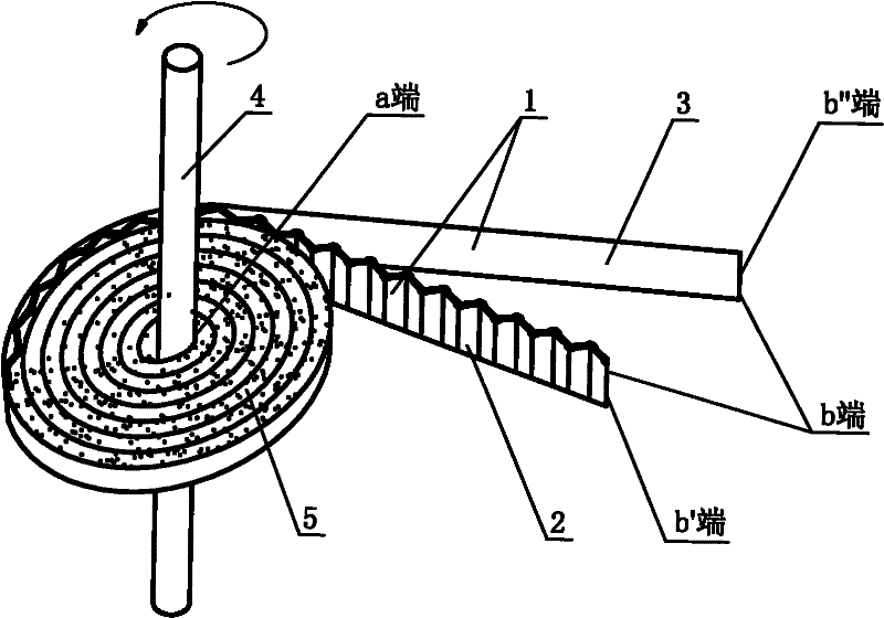
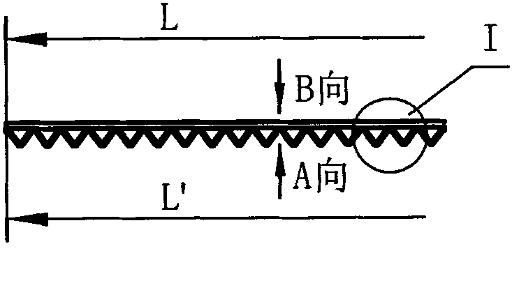
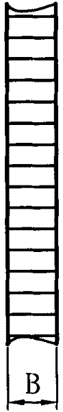
[0033] Such as Figure 1 to Figure 5 as well as Figure 10 to Figure 11As shown, a method for making a fine orifice plate, the method includes the following steps: pressing a straight stainless steel strip with a length of 100m, a thickness of 0.25mm, and a width of 10mm to form a wave pitch P=1mm and a wave height H=0.8mm . A corrugated strip 2 with a sinusoidal curved surface, the corrugated strip 2 has a length L'=82m, a thickness S=0.25mm, and a width B=10mm. Match the corrugated belt 2 with a straight belt 3 made of stainless steel with a length L=87m, a thickness M=0.25mm, and a width B =10mm. Align to form a wave flat belt 1 with one side being a flat surface (i.e. C surface) and the other side being a wave surface (i.e. D surface), and then the wave flat belt 1 starting end (i.e. end a) is fixed on the central axis 4. The central shaft 4 is a hollow tube shaft whose cross section is a ring-shaped plastic material with an inner diameter of 100 mm and an outer diameter...

Embodiment 2

[0035] Such as figure 1 , Figure 10 to Figure 13 Shown, a kind of method for making fine orifice plate, described method comprises the steps: take one side of length L=150m to be flat surface (being C surface) the other side has wave surface (being D surface) The wave flat belt 1 of stainless steel material, the wave surface shape of the wave flat belt 1 is a sinusoidal wave belt 2, the thickness M' of the wave flat belt 1 from the flat surface (ie C surface) to the wave valley point (ie point d) =1.5mm, M' is the vertical distance from the flat surface (C face) in the wave flat band 1 to the valley point (d point) of the wave surface, the width B of the wave flat band 1"=5mm, the wave surface of the wave flat band 1 The wave distance P=1.5mm, wave height H=1.5mm.The initial end (being a end) of this wave flat band is fixed on the central axis.The section of the plastic material that central axis 4 is inner diameter 100mm, outer diameter 120mm is annulus Shaped hollow tube ...

Embodiment 3

[0037] Such as Figure 1 to Figure 6 as well as Figure 10 to Figure 11 As shown, a method for making a micro-orifice plate, its steps are basically the same as in Embodiment 1, the difference is that the wave surface shape of the wave band 2 is arc-shaped, that is, the wave surface shape of the wave flat band 1 is arc-shape. The central axis 4 is a solid axis with a circular cross section. The end end (ie b" end) of the flat strip 3 is bonded. The material of the flat strip 1 is copper.


PUM

PropertyMeasurementUnit
thicknessaaaaaaaaaa
widthaaaaaaaaaa
widthaaaaaaaaaa

Abstract

The invention relates to a method for manufacturing a tiny-pore plate by using a wave flat belt, comprising the following steps of: overlapping a wave-shaped belt (2) and a flat belt (3) to form a wave flat belt (1); fixing the starting end of the wave flat belt (1) on a center shaft (4); winding the wave flat belt (1) on the center shaft (4) for a plurality of circles by taking the center shaft (4) as a center; and fixing the termination end of the wave flat belt (1) after the winding so as to obtain the tiny-pore plate (5). Another method provided by the invention comprises the steps of: fixing the starting end of a wave flat belt (1) which has a flat surface at one side and a wave-shaped curved surface at the other side on a center shaft (4); winding the wave flat belt (1) on the center shaft (4) for a plurality of circles by taking the center shaft (4) as the center; and fixing the termination end of the wave flat belt (1) after the winding is ended so as to obtain the tiny-pore plate (5). The method provided by the invention is simple; and the tiny-pore plate has good quality and low manufacturing cost.

Description

technical field [0001] The invention relates to a manufacturing technology of a micro-orifice plate, in particular to a method for manufacturing a micro-orifice plate by using wave flat tape. The method of the present invention is applicable to the making of various fine orifice plates, and the method of the present invention is especially applicable to through-hole nominal diameter≤2mm, plate thickness≥0.5mm, through-hole area (through-hole number×single-hole area equals through-hole area) and hole Fabrication of dense and regularly arranged fine orifice plates with a plate area ratio approaching π / 4. Background technique [0002] Today's fine orifice plates are widely used in the filtration and purification of fluids (liquids include water, oil, organic solvents and their solutions, etc., gases include air, exhaust gases, chemical process gases, flue gases, etc.), and as support for the filter material layer. Or directly used as filter screens and melt-spinning through-ho...

Claims


Application Information

Patent Timeline
Patent Type & Authority Applications(China)
IPC IPC(8): B32B3/26B32B3/24
Inventor 朱文蔚朱晓峰朱国富
Owner 朱文蔚
Why Eureka
Try Eureka