
Device and method for realizing conversion between metal rectangular waveguides and microstrip lines

A rectangular waveguide and waveguide conversion technology, applied in the field of electromagnetic wave transmission, can solve the problems of frequency limitation, narrow working frequency band, and small application range, etc., and achieve the effect of simple manufacturing process, simple structure, and wide application range

Inactive Publication Date: 2011-09-07
UNIV OF SCI & TECH OF CHINA
View PDF3 Cites 10 Cited by
  • Summary
  • Abstract
  • Description
  • Claims
  • Application Information

AI Technical Summary

Problems solved by technology

The side wall of the waveguide forms a groove of the metallization layer on the substrate, and the upper and lower metallization layers of the substrate are conductively penetrated and contacted to surround the groove. This conversion device has a fine and complex structure, is difficult to process, and has a frequency limit.
[0005] The above two converters between the microstrip line and the waveguide have complex structures, difficult processing, and cannot be mass-produced and processed. Moreover, the working frequency band is narrow and the scope of application is small.

Method used


Image

  • Device and method for realizing conversion between metal rectangular waveguides and microstrip lines
  • Device and method for realizing conversion between metal rectangular waveguides and microstrip lines
  • Device and method for realizing conversion between metal rectangular waveguides and microstrip lines

Examples


Embodiment Construction

[0026] In order to enable those skilled in the art to better understand the technical solutions in the present invention, the technical solutions in the embodiments of the present invention will be clearly and completely described below in conjunction with the drawings in the embodiments of the present invention. Obviously, the described The embodiments are only some of the embodiments of the present invention, not all of them. Based on the embodiments of the present invention, all other embodiments obtained by persons of ordinary skill in the art without making creative efforts shall fall within the protection scope of the present invention.

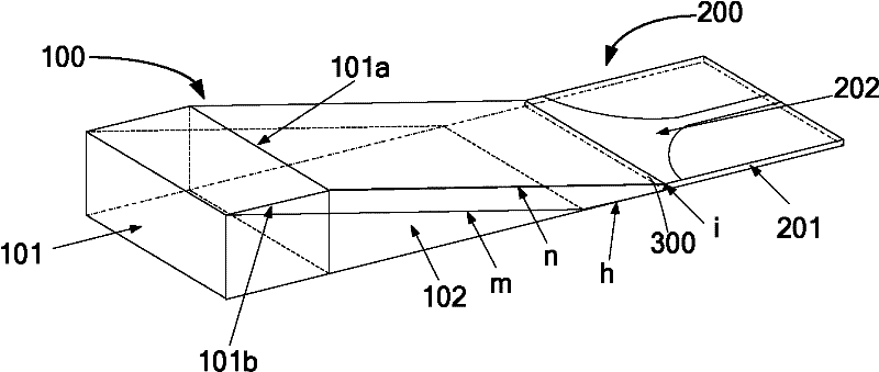
[0027] see figure 1 , figure 1 Shown is a schematic structural diagram of a conversion device between a metal rectangular waveguide and a microstrip line according to an embodiment of the present invention. The device includes: a waveguide conversion end 100, and a microstrip line conversion end 200 connected to the waveguide conversio...


PUM


Abstract

The invention discloses a method for realizing conversion between metal rectangular waveguides and microstrip lines. The device comprises a waveguide converter and a microstrip line converter connected with the waveguide converter. The waveguide converter comprises a waveguide section and a waveguide transition section, wherein the waveguide section comprises a wide edge and a narrow edge; the waveguide transition section is formed by retracting the narrow edge of the waveguide section to a connecting surface between the waveguide converter and the microstrip line converter in a linear lowering way; and a dielectric body is uniformly filled into the wide edge of the waveguide section. The microstrip converter comprises a baseband board and the microstrip lines, wherein the width of the baseband board is the same as that of the metal rectangular waveguide; and the microstrip lines are arranged on the baseband board. Electromagnetic waves are transmitted from the waveguide converter to the microstrip line converter to realize effective conversion between waveguide propagation and microstrip line propagation. The device only relates to a linear planar structure, is simply structure and simple and convenient to manufacture; moreover, a frequency-sensitive geometrical structure is unrelated, and the working frequency range of the device is only limited by own working frequency range of the waveguide, so the device has the characteristic of wideband.

Description

technical field [0001] The invention relates to the technical field of electromagnetic wave transmission, in particular to a conversion device and a conversion method between a metal rectangular waveguide and a microstrip line. Background technique [0002] In the field of electromagnetic wave transmission, especially in the process of microwave or millimeter wave transmission, it is usually necessary to transmit microwave signals between waveguides and microstrip lines. Between the energy conversion device. [0003] In the prior art, a converter between a microstrip line and a metal rectangular waveguide adopts a flat plate structure. A through hole is provided at the intersection of the plate and the metal rectangular waveguide. The independent piece includes a microstrip line terminal and can be placed on the through hole. An adjustment is made so that the end of the microstrip line coincides with the end of a microstrip line on the plate. The conversion device has a co...

Claims


Application Information

Patent Timeline
IPC IPC(8): H01P1/16
Inventor 汪佳娣陈卫东周凌云章恒斌陆广华
Owner UNIV OF SCI & TECH OF CHINA
Features
  • Generate Ideas
  • Intellectual Property
  • Life Sciences
  • Materials
  • Tech Scout
  • Unparalleled Data Quality
  • Higher Quality Content
  • 60% Fewer Hallucinations
Learn More