
Switch power controller and valley bottom switching method thereof

A switching power supply and controller technology, applied in the direction of control/regulation systems, instruments, electrical components, etc., can solve the problems of hindering Pon reduction, energy loss, high switching frequency, etc., and achieve the effect of alleviating electromagnetic interference and improving efficiency

Active Publication Date: 2011-09-14
GIANTEC SEMICON LTD
View PDF2 Cites 15 Cited by
  • Summary
  • Abstract
  • Description
  • Claims
  • Application Information

AI Technical Summary

Problems solved by technology

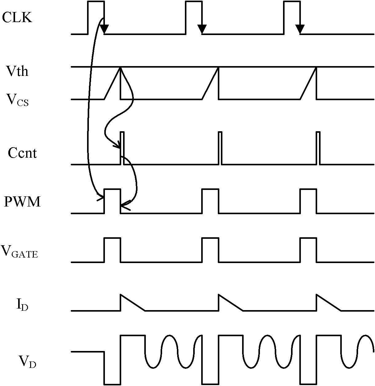
[0012] 2. The conduction of the power switch leads to a linear increase of the coil current on the primary side of the transformer, which in turn leads to a linear increase of the Vcs signal;
[0013] 3. When the amplitude of the Vcs signal reaches the amplitude of the threshold value Vth of the PWM comparator, the PWM comparator flips, and the PWM signal becomes low, which in turn causes the power switch to be cut off;
[0014] 4. The cut-off of the power switch causes the Vcs signal to return to zero, and the PWM comparator is reversed;
[0024] However, the disadvantage of this system is that it can only predict the moment of the first valley after the end of demagnetization. In the valley switching mode, the power switch SW can only be turned on at the first valley moment after the end of demagnetization. Therefore, as the load current decreases, the switch The frequency will gradually increase
The increase in switching frequency will first hinder the P on In addition, in each switching process, the current of the primary coil of the transformer will flow through the power switch to cause energy loss, and the energy loss will increase with the increase of the switching frequency
[0025] In addition to energy loss, the high rate of change of current and voltage during each power switch transition also poses serious electromagnetic interference (EMI) problems

Method used


Image

  • Switch power controller and valley bottom switching method thereof
  • Switch power controller and valley bottom switching method thereof
  • Switch power controller and valley bottom switching method thereof

Examples


Embodiment Construction

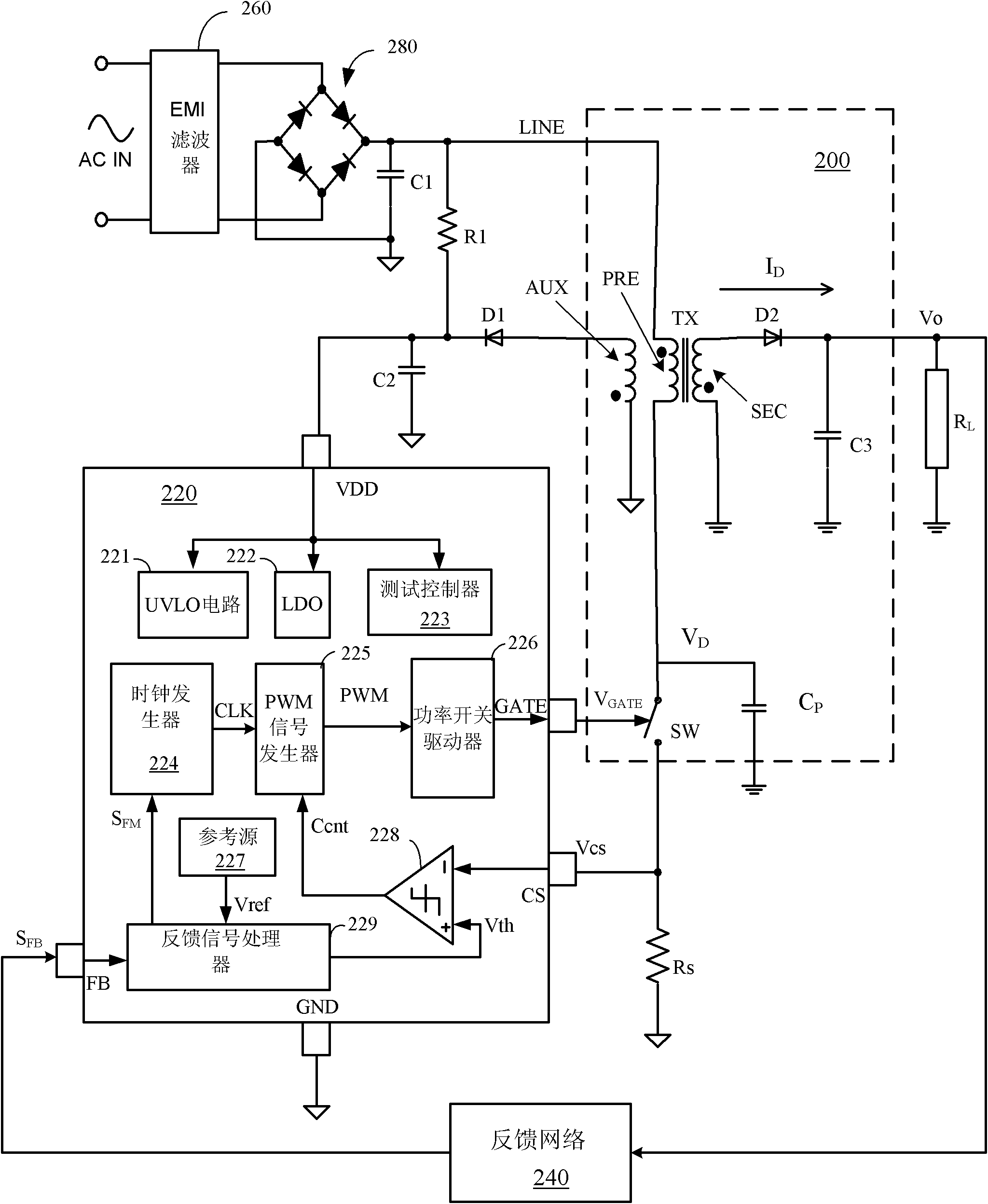
[0058] Figure 7 The switching power supply system of the present invention is illustrated, Figure 8 example Figure 7 working timing. refer to Figure 7 As shown, the switching power supply system includes an EMI filter 360 , an input rectifier 380 , a power converter 300 , a switching power supply control chip 320 and a feedback network 310 . The EMI filter 360 , the input rectifier 380 and the power converter 300 can use conventional structures, which will not be repeated here.

[0059] and figure 2 Compared with the switching power supply control chip 220 in the present embodiment, a valley predictor 326 and a valley clock generator 328 are added inside the switching power supply control chip 320 . The switching power supply control chip 320 additionally provides a pin RVM for the valley predictor 326, which is used to connect an external resistor R ext . An input terminal of the valley predictor 326 is connected to the feedback signal processor 325 , and an outpu...


PUM


Abstract

The invention relates to a switch power controller and a valley bottom switching method thereof, which are applied to a switch power system. The switch power system comprises a switch power converter, wherein the switch power converter comprises a power switch and is used for controlling a first voltage of the primary side of the switch power converter. In the switch power controller, a feedback signal processor is used for generating an indication signal according to a feedback signal related to the first voltage; the indication signal indicates the oscillation information of the first voltage; a valley bottom predictor is used for generating a prediction signal for predicting a valley bottom moment of the first voltage according to the indication signal; a valley bottom clock generator is used for triggering an edge of a second clock signal at a first prediction signal behind an edge of a first clock signal so as to synchronize the edge of the second clock signal to the valley bottom moment of the first voltage; and a pulse width modulator is used for triggering a pulse width modulation signal by using the second clock signal so as to control the switch-on and switch-off of the power switch.

Description

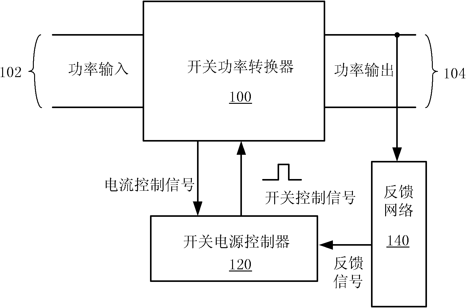
technical field [0001] The invention relates to the field of integrated circuits, and more specifically, the invention relates to an implementation of a power switch adaptive valley switching mode for a switching power supply controller chip. Background technique [0002] Due to the many advantages compared with traditional linear power supplies, such as higher efficiency, lower standby power consumption, lower cost, smaller size and lighter weight, switching power supplies are more and more widely used in various electronic devices. [0003] figure 1 The basic block diagram of the most widely used current mode switching power supply system is shown. The system includes a switching power converter 100 , a switching power supply controller 120 and a feedback network 140 . The switching power converter 100 has a power input port 102 and a power output port 104 . The switching power converter 100 interacts with the switching power supply controller 120 through switching con...

Claims


Application Information

Patent Timeline
IPC IPC(8): H02M3/335
Inventor 王为黄剑锋杨彪朱臻沈国平吴一一王多慧
Owner GIANTEC SEMICON LTD
Learn More