Intelligent lead aligner
A wire-aligner, intelligent technology, applied in the direction of instruments, measuring devices, measuring electricity, etc., can solve problems such as affecting the accuracy of the secondary circuit wiring of the power system, error-prone cable code verification, affecting the safe operation of the power grid, etc. Ease of implementation, low cost, improved accuracy and reliability
- Summary
- Abstract
- Description
- Claims
- Application Information
AI Technical Summary
Problems solved by technology
Method used
Image

Examples
Embodiment 1
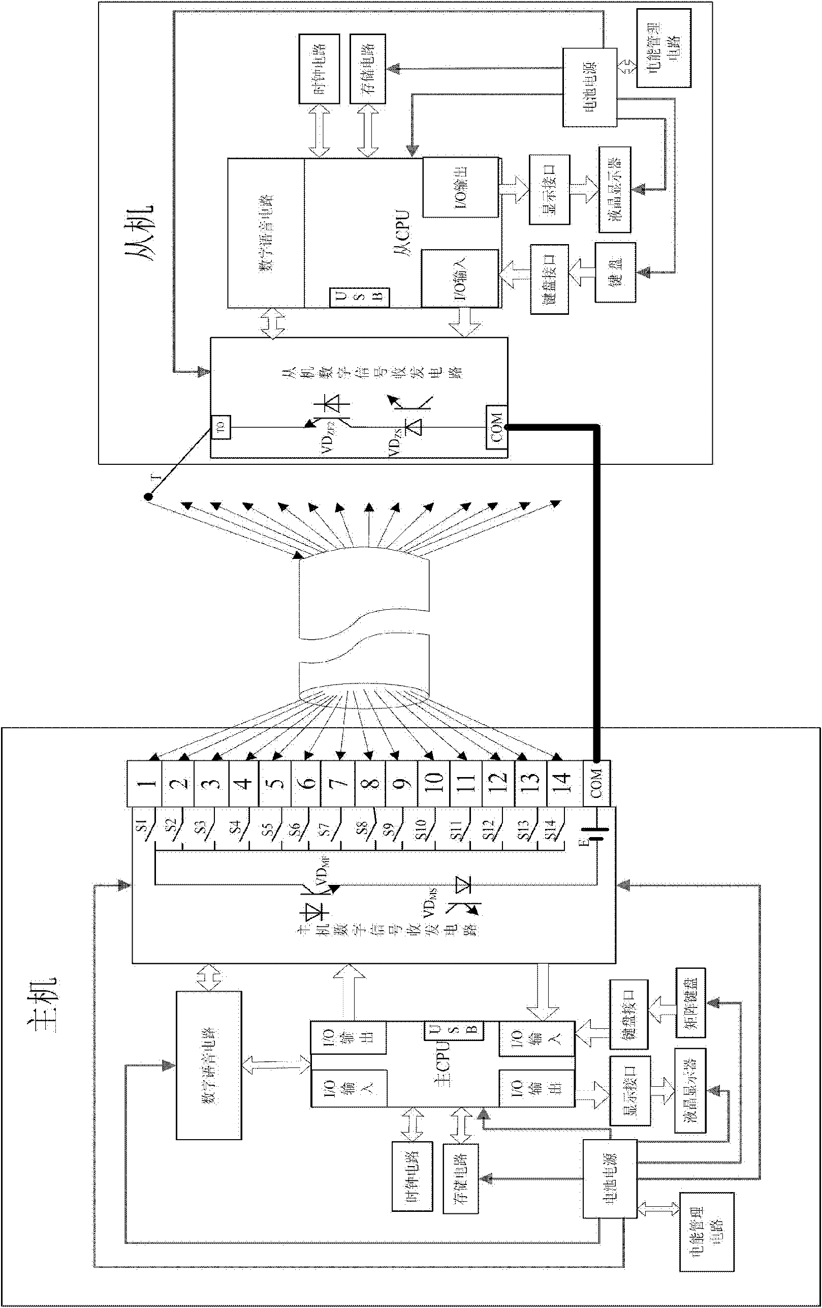
[0029] Such as figure 1 Shown by S, VD MF , VD ZF , E, public land, VD MS , VD ZS , T, and cables can form a loop, which can not only detect the continuity of the cable, but also transmit digital signals. CPU controls VD MF , VD ZF It can realize on-line control, digital signal transmission, VD MS , VD ZS The output is connected to the CPU to realize the reception of on-off signals and digital signals. After booting up, it first enters the line work, the host repeatedly scans the electronic switches (that is, makes S1 to S14 conduction in turn, and only one electronic switch is conducted at each moment), VD MF , VD ZF Set the open state, when the slave probe is connected to one of the 14 cables, a current is generated in the loop to drive VD MS , VD ZS When it is turned on, the output signals are sent to the master and the slave respectively. The master judges which cable is connected according to the position of S, and uses VD MF To control the on-off of the loop,...
Embodiment 2
[0034] Embodiment 2: Same as Embodiment 1, the difference is that the probe (T) is replaced by another group of electronic switches, and this other group of electronic switches includes 14 electronic switches, and the wiring form is connected with the electronic switch at the host end Exactly the same (or symmetrical to each other), one end of the other group of electronic switches is respectively connected to the 14 wires of the cable, and the other end of the other group of electronic switches is short-circuited together and connected to one end of the slave branch. The other end of the slave-to-line branch is connected to the common ground (COM).
PUM
 Abstract
Description
Claims
Application Information
 - Generate Ideas
- Intellectual Property
- Life Sciences
- Materials
- Tech Scout
- Unparalleled Data Quality
- Higher Quality Content
- 60% Fewer Hallucinations
Browse by: Latest US Patents, China's latest patents, Technical Efficacy Thesaurus, Application Domain, Technology Topic, Popular Technical Reports.
© 2025 PatSnap. All rights reserved.Legal|Privacy policy|Modern Slavery Act Transparency Statement|Sitemap|About US| Contact US: help@patsnap.com