Duplex deaerator

A deaerator and duplex technology, applied in the field of duplex deaerators, can solve problems such as explosion, catalyst bed overheating, catalyst damage, etc., and achieve the effects of avoiding damage, avoiding overheating phenomenon and preventing explosion.

Inactive Publication Date: 2011-10-05
SUZHOU EVERYWHERE GAS EQUIP
View PDF5 Cites 3 Cited by
  • Summary
  • Abstract
  • Description
  • Claims
  • Application Information

AI Technical Summary

Problems solved by technology

Due to the large amount of heat released by the chemical reaction of hydrogen and oxygen, the catalyst bed will be overheat

Method used


Image

  • Duplex deaerator
  • Duplex deaerator

Examples


Embodiment Construction

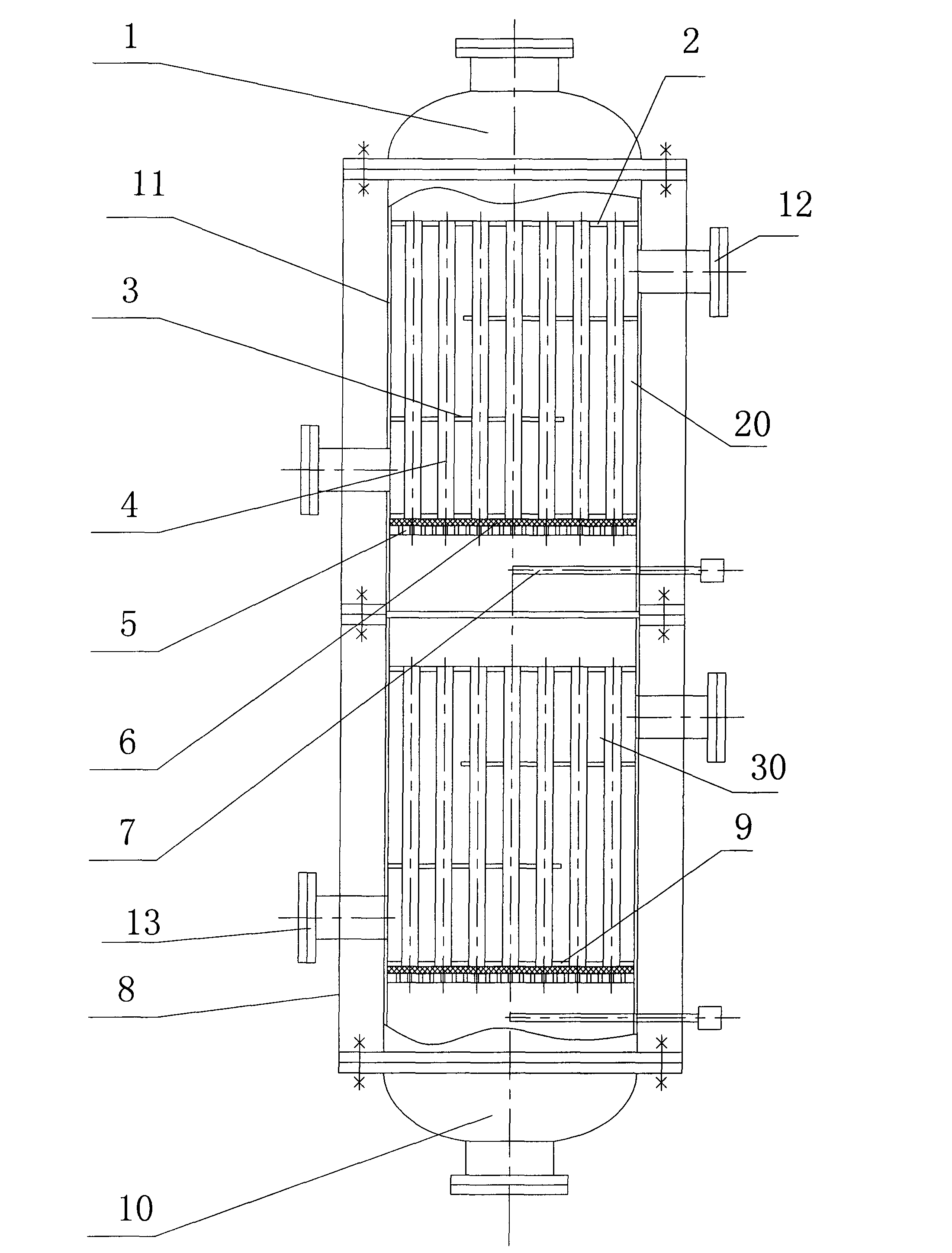
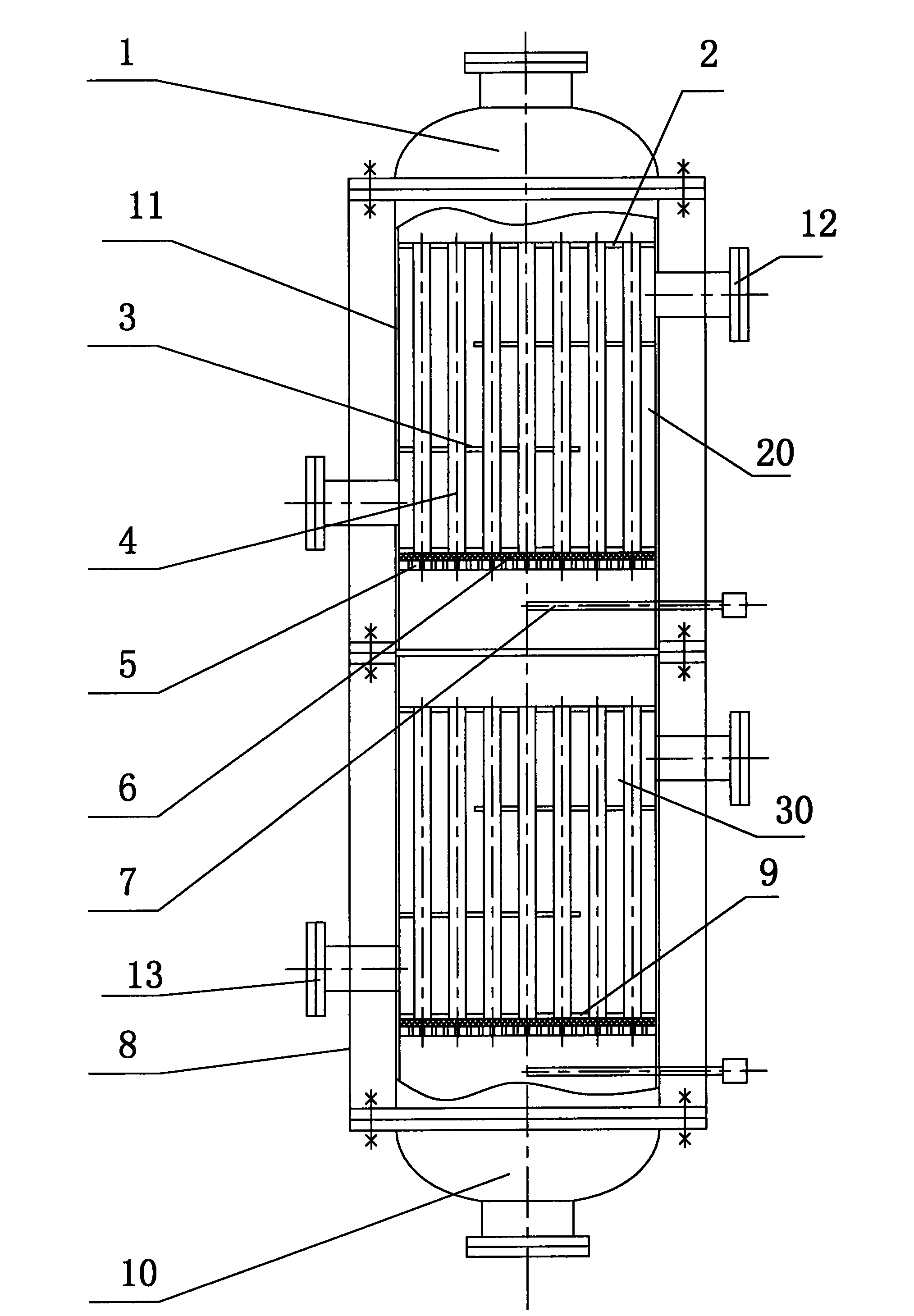
[0014] See figure 1 The compound deaerator includes two compound deaerator units 20, 30, a raw material gas inlet head (air distributor) 1, a product gas outlet head (air distributor) 10.

[0015] The two duplex deaerator units 20 and 30 have the same structure, and both include the shell 11, the upper flange 2, the lower flange 9, the column pipe 4, the stainless steel wire mesh 5, the sieve plate 6, and the thermocouple (thermometer) connection pipe 7, Insulation layer 8, baffle 3, etc. The lower end of the housing of the multiple deaerator unit 20 is connected to the upper end of the housing of the multiple deaerator unit 30.

[0016] The peripheries of the upper flange 2 and the lower flange 9 are respectively connected to the inner wall of the shell close to the upper and lower ends of the shell. The upper and lower ends of the tube 4 respectively pass through the upper flange and the lower flange, and each tube is in the circumferential direction. It is in sealed contact wi...


PUM


Abstract

The invention provides a duplex deaerator capable of preventing catalyst damages and even explosion danger due to the phenomenon of temperature runaway of a catalyst bed layer. The duplex deaerator comprises a shell, wherein a tube pass through which oxygen-containing hydrogen can pass and a shell pass through which heat exchanging media can pass are arranged in the shell; the tube pass is not communicated with the shell pass; and a deoxidization catalyst is arranged in the tube pass.

Description

Technical field [0001] The invention relates to a compound deaerator, in particular to a compound deaerator used for removing a higher proportion of oxygen in hydrogen to prepare high-purity hydrogen. Background technique [0002] In the production process of many chemical companies, such as the production of synthetic ammonia, sodium chlorate, etc., a large amount of hydrogen with high oxygen content is emitted (the oxygen content in hydrogen is between 3-4%), due to the hydrogen and oxygen in the tail gas The ratio is on the edge of the explosion limit, and it is difficult to remove the oxygen in the hydrogen. Many chemical companies directly vent the exhaust gas for safety reasons. This has a certain impact on the environment and also emits a large amount of hydrogen with extremely high use value. . [0003] Nowadays, deaerators are generally used to remove oxygen from hydrogen. The housing of the deaerator is equipped with a deoxygenation catalyst, and oxygen-containing hydro...

Claims


Application Information

Patent Timeline
IPC IPC(8): C01B3/58
Inventor 吴天月葛来香
Owner SUZHOU EVERYWHERE GAS EQUIP
Why Eureka
Try Eureka