Device and method for suppressing dilution of oil

A suppression device and engine oil technology, applied in the direction of engine control, electrical control, mechanical equipment, etc., can solve problems such as no consideration, increased fuel, low engine temperature, etc.

Inactive Publication Date: 2011-10-12
TOYOTA JIDOSHA KK
View PDF16 Cites 14 Cited by
  • Summary
  • Abstract
  • Description
  • Claims
  • Application Information

AI Technical Summary

Problems solved by technology

[0011] However, according to the above-mentioned background technology, for example, a vehicle equipped with an automatic engine stop and start device (so-called fuel saving system or stop idling system) that repeatedly starts and stops the engine more frequently is not considered.
As a result, there are technical problems such as the temperature of the engine becoming relatively low, the increase of non-volatile fuel, and the dilution of engine oil caused by unburned fuel beyond expectations.

Method used


Image

  • Device and method for suppressing dilution of oil
  • Device and method for suppressing dilution of oil
  • Device and method for suppressing dilution of oil

Examples


no. 1 Embodiment approach

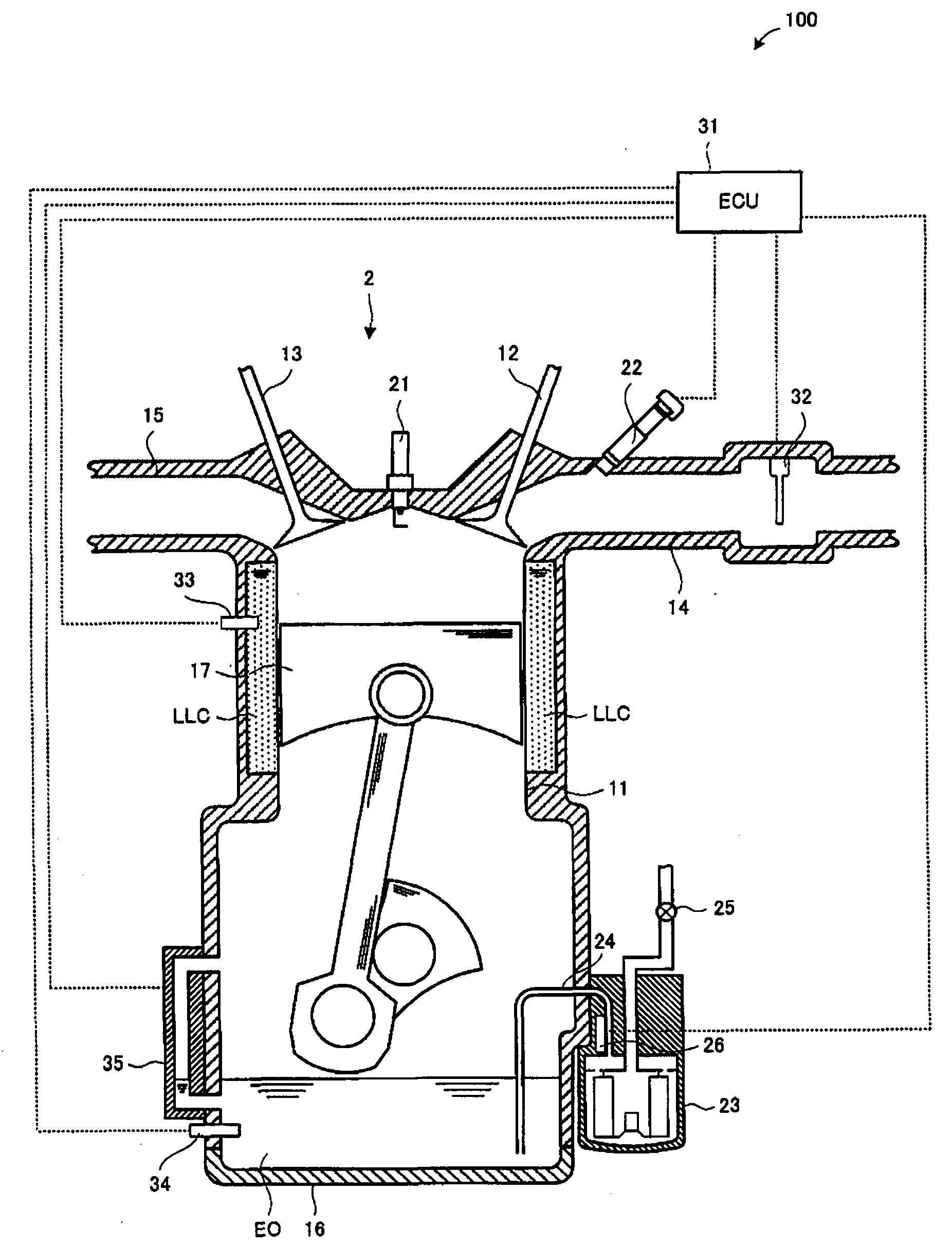
[0071] refer to figure 1 and figure 2 , the first embodiment of the oil dilution suppression device according to the present invention will be described. it's here, figure 1 It is a block diagram showing the configuration of the oil dilution suppression device according to the first embodiment.

[0072] figure 1 Among them, the engine 1 equipped with the vehicle (not shown) equipped with the oil dilution suppression device 100 includes a cylinder 11, an intake valve 12, an exhaust valve 13, an intake passage 14, an exhaust passage 15, an oil pan 16, and a piston. 17. Spark plug 21, fuel injection valve 22, oil filter 23 and oil heater 26.

[0073] The engine oil EO stored in the oil pan 16 flows into the oil filter 23 through the oil inflow passage 24 . The engine oil EO passed through the oil filter 23 is sucked by the oil pump 25 and supplied to a main station not shown here. The fuel injection valve 22 is controlled by an ECU (Electronic Control Unit: electronic cont...

no. 2 Embodiment approach

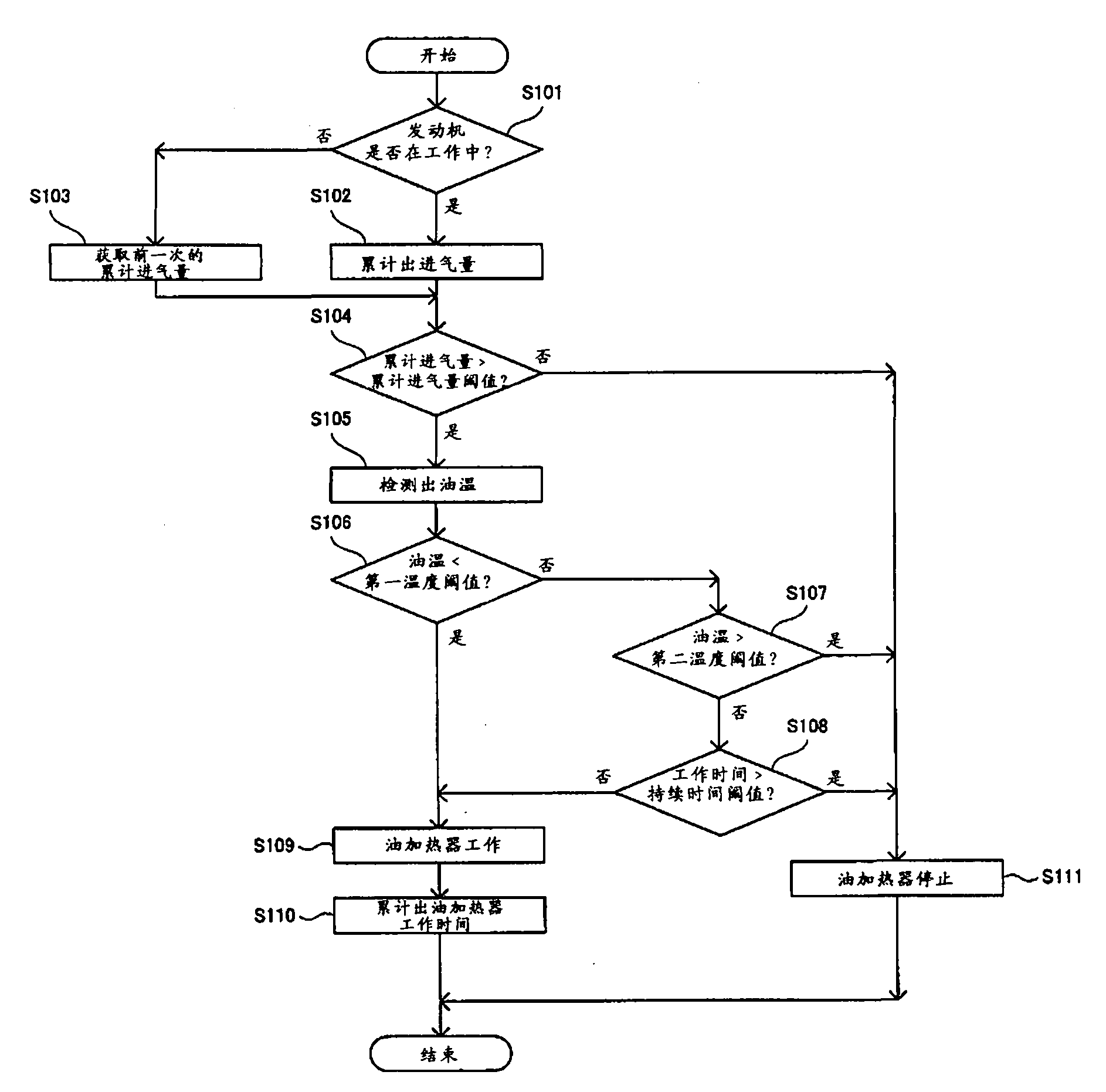
[0122] refer to Figure 5 A second embodiment of the oil dilution suppression device of the present invention will be described. In the second embodiment, the configuration is the same as that of the first embodiment except that the oil dilution suppression process executed by the ECU is different. Therefore, when describing the second embodiment, descriptions that overlap with the first embodiment will be omitted, and common parts in the drawings will be denoted by the same symbols, and reference will be made to Figure 5 Only what is fundamentally different is described. it's here, Figure 5 is the same as figure 2 It is a flowchart of oil dilution suppression processing executed by the ECU according to the present embodiment with the same principle.

[0123] (when the oil heater is off)

[0124] Figure 5Among them, when the oil heater 26 is off (ie, not in the oil heating mode), first, the ECU 31 detects the state of the vehicle (step S301). Specifically, for examp...

no. 3 Embodiment approach

[0145] refer to Image 6 , and a third embodiment of the oil dilution suppression device according to the present invention will be described. In the third embodiment, the configuration is the same as that of the first embodiment except that the oil dilution suppression process executed by the ECU is different. Therefore, when describing the third embodiment, descriptions that overlap with the first embodiment will be omitted, and common parts in the drawings will be denoted by the same symbols, and reference will be made to Image 6 Only what is fundamentally different is described. it's here, Image 6 is the same as figure 2 It is a flowchart of oil dilution suppression processing executed by the ECU according to the present embodiment with the same principle.

[0146] (when the oil heater is off)

[0147] Image 6 In this case, when the oil heater 26 is off (that is, not in the oil heating mode), first, the ECU 31 obtains the oil temperature of the engine oil EO thro...


PUM


Abstract

An oil dilution suppression device (100) is mounted on a vehicle equipped with an engine (1) capable of using an alcohol fuel. The oil dilution suppression device comprises an intake amount integration means (31) for calculating an integrated intake amount by integrating the quantity of air sucked into the engine during operation of the engine, a temperature detection means (34) for detecting thetemperature of the engine oil in the engine, and a control means (31) for so controlling the vehicle that the vehicle is moved to an oil heating mode for raising the temperature of the oil under suchconditions that the calculated integrated intake amount is larger than the integrated intake amount threshold and the detected temperature of the oil is lower than a first temperature threshold.

Description

technical field [0001] The present invention relates to an oil dilution suppression device and method for suppressing dilution of engine oil by ethanol fuel, for example, in a vehicle including an engine capable of using ethanol fuel. Background technique [0002] Since the fuel is mixed into the engine oil, when the engine oil is diluted, problems such as a decrease in the lubricity of the engine oil occur. [0003] As such a device, for example, an internal combustion engine has been proposed that operates an oil heater to increase the temperature of lubricating oil when sub-injections such as pilot injection and vertical injection are performed before and after main injection (see Patent Document 1). Alternatively, a device has been proposed that sets a fuel injection timing based on a count value of a dilution counter related to oil dilution when a diesel engine is started (see Patent Document 2). Alternatively, a device has been proposed that estimates the degree of f...

Claims


Application Information

Patent Timeline
Patent Type & Authority Applications(China)
IPC IPC(8): F01M5/00
CPCF01M1/10F01M5/001F01M2001/165F02D41/0025F02D41/068F02D41/18F02D2200/023F02D2250/11F02N11/0814F02N19/04
Inventor 金井弘
Owner TOYOTA JIDOSHA KK
Why Eureka
Try Eureka