2DPSK (Differential Phase Shift Keying) demodulation circuit, demodulation method and wireless signal receiver system

A technology for demodulating circuits and signals, applied in the field of implantable bioelectronics, which can solve problems such as chip area, power consumption, high cost, high operating frequency of the demodulated chip, and increased energy consumption, achieving low complexity and high efficiency The effect of unit bit energy consumption and low power consumption

Inactive Publication Date: 2011-10-19
SOUTH CHINA UNIV OF TECH
View PDF1 Cites 4 Cited by
  • Summary
  • Abstract
  • Description
  • Claims
  • Application Information

AI Technical Summary

Problems solved by technology

Both of these two related demodulation methods need to obtain a synchronous clock for coherent demodulation, resulting in a complex structure and increased energy consumption, resulting in a large chip area, power consumption, and cost after system integration, and the demodulation chip needs to bear more high operating frequency
Therefore, the traditional PSK coherent demodulation method is not suitable for implantable medical integrated chips, civilian consumer electronics communication fields, family miniaturized medical wireless equipment, etc.

Method used


Image

  • 2DPSK (Differential Phase Shift Keying) demodulation circuit, demodulation method and wireless signal receiver system
  • 2DPSK (Differential Phase Shift Keying) demodulation circuit, demodulation method and wireless signal receiver system
  • 2DPSK (Differential Phase Shift Keying) demodulation circuit, demodulation method and wireless signal receiver system

Examples


Embodiment Construction

[0027] The present invention will be further described below in conjunction with the accompanying drawings.

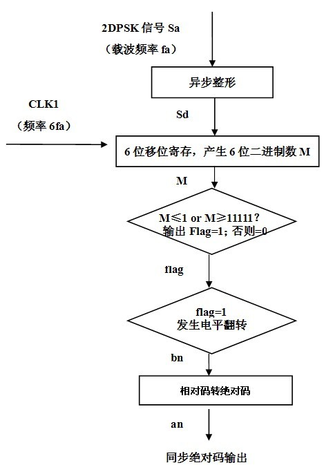
[0028] figure 1 The principle block diagram of the 2DPSK signal demodulation method provided for the present invention includes the following parts: asynchronous shaping, N-bit shift register (N=6 of the N-bit shift register in this embodiment), mathematical threshold judgment, trigger flip, Relative code to absolute code.

[0029] figure 1 The signal flow and demodulation process in is: 2DPSK signal Sa enters asynchronous shaping, realizes the conversion of 2DPSK signal Sa from analog level to digital level, and outputs digital 2DPSK signal Sd with stable duty cycle.

[0030] With a digital clock that is N times the carrier frequency fc of the 2DPSK signal, the digitized 2DPSK signal is sent to an N-bit shift register, and an N-bit binary number M (of N Typical value can be 6). For example, under the control of the asynchronous clock signal CLK1 which is 6 times t...


PUM


Abstract

The invention provides a 2DPSK (Differential Phase Shift Keying) demodulation circuit, a demodulation method and a wireless signal receiver system. The 2DPSK demodulation circuit comprises an asynchronous shaping circuit, an N-bit shift register, a mathematics threshold decider, a trigger turnover circuit, a synchronous adjustment trigger and a relative code to absolute code circuit, which are connected in sequence. Secondary down frequency conversion used in the 2DPSK wireless signal receiver system is combined with a simple and effective digital demodulation method disclosed by the invention. According to the demodulation method, the demodulation is carried out by using the circuit. The working frequency of the demodulation circuit is reduced. A difficult and complex frequency doubling carrier synchronous tracking circuit or Costas ring circuit is unnecessary, thus the system can be realized by having the advantages of low complexity, low power consumption and high efficiency so that the unit bit energy consumption of a receiving system is reduced obviously.

Description

technical field [0001] The invention relates to the field of implantable bioelectronic technology, in particular to a 2DPSK demodulation method, a demodulation circuit and a wireless signal receiver system based on wireless digital communication technology with low complexity and low power consumption. Background technique [0002] In modern wireless communication systems, modulation and demodulation technology is an essential link, and its performance is related to the performance of the entire communication system. Digital modulation and demodulation technology has been widely used in modern wireless communication systems because of its good anti-noise performance and excellent bit error rate performance. With the development trend of miniaturization, digitalization and large-scale integration of modern communication systems, the market demand for communication systems with low complexity, low power consumption, low cost and good bit error rate performance is increasing, s...

Claims


Application Information

Patent Timeline
Patent Type & Authority Applications(China)
IPC IPC(8): H04L27/22
Inventor 赵明剑李斌王博吴朝晖
Owner SOUTH CHINA UNIV OF TECH
Why Eureka
Try Eureka