Low temperature co-fired ceramic (LTCC) filter production process and LTCC filter

A manufacturing process and filter technology, applied to waveguide devices, impedance networks, electrical components, etc., can solve problems such as high cost, achieve high conductivity, increase degrees of freedom, and reduce disconnection and deformation

Active Publication Date: 2011-11-02
SHENZHEN MICROGATE TECH
View PDF3 Cites 16 Cited by
  • Summary
  • Abstract
  • Description
  • Claims
  • Application Information

AI Technical Summary

Problems solved by technology

[0005] The purpose of the present invention is to solve the high cost problem caused by the laser drilling and microhole gr

Method used


Image

  • Low temperature co-fired ceramic (LTCC) filter production process and LTCC filter
  • Low temperature co-fired ceramic (LTCC) filter production process and LTCC filter
  • Low temperature co-fired ceramic (LTCC) filter production process and LTCC filter

Examples


Embodiment 1

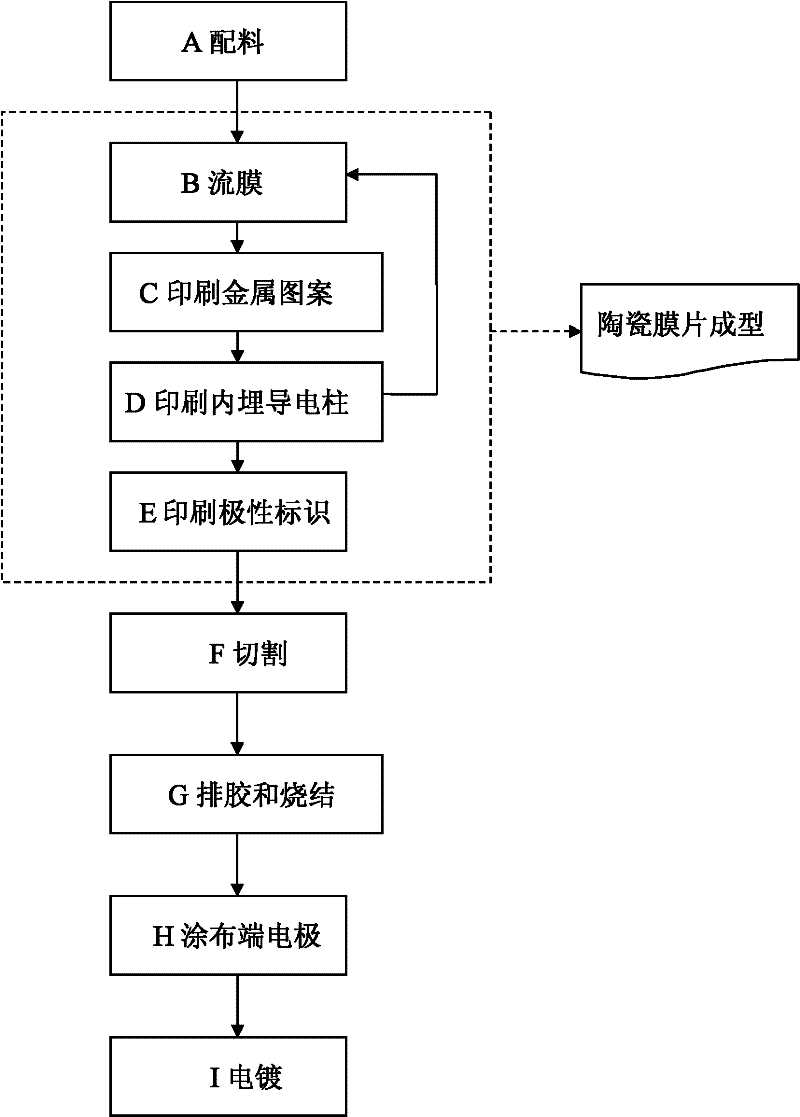
[0074] Among them, steps B, C, D, and E are ceramic diaphragm forming steps, refer to Figure 5 As shown in , a specific production process is taken as an example to describe in detail. First, step B is carried out, and the ceramic slurry is cast into a ceramic diaphragm, and the casting is repeated to form a ceramic substrate 101 with a certain thickness, which we call the lower substrate; Step C is performed on the lower substrate, and Ag The paste is printed into a metal pattern to form a grounding conductor 102; then step D is performed several times, and the method of printing a metal bump with a printed Ag paste—a method of covering a ceramic film is repeated for a certain number of times to form the first embedded conductive column 103; and then operate Step C, printing the first capacitive substrate 104 and the second capacitive substrate 105; followed by step D, printing the embedded conductive pillars to form the second embedded conductive pillars 106 and the third e...

Embodiment 2

[0077] refer to Image 6 , and combined with Figure 4 As shown in , another specific manufacturing step for forming the ceramic diaphragm is as follows: firstly cast ceramic slurry to form a ceramic raw material film, repeat casting to form the lower substrate 201; print metal patterns on the substrate to form the ground shielding layer 202, The coating electrode 202 will be connected to the external ground terminal electrodes 24, 25; the plate electrodes 203, 204 and the ground shielding layer 202 form two ground capacitances; the plate electrodes 207, 208 and the lead-out electrodes 211, 212 form input / output electrodes respectively , wherein the lead-out electrodes 211, 212 will be connected to the input and output electrodes 22, 23; the plate electrodes 207, 208 are respectively connected to the plate electrodes 213, 214 through a group of embedded conductive columns 209, 210; the plate electrodes 213, 214 are connected to the lead-out electrodes 211, 212 form an input / o...


PUM

PropertyMeasurementUnit
Thicknessaaaaaaaaaa

Abstract

A low temperature co-fired ceramic (LTCC) filter production process and a LTCC filter relates to a production process of the LTCC filter. A high cost problem of a dry process of the LTCC filter caused by employing processes of laser drilling and micropore grouting can be solved. The production process comprises the following steps: A. preparing slurries; B. flowing the slurries so as to obtain membrane; C. printing metal patterns; D. printing and forming embedded conductive poles which means that a mode of repeatedly printing is employed so as to form embedded conductive poles ; E. printing polarity identification; F. cutting; G. performing binder removal and sintering; H. coating terminal electrodes; I. electroplating. The several groups of embedded conductive poles not only play a role of conductive interconnection but also play the vital role on electrical property of the filter, wherein the embedded conductive poles are as a plurality of independent resonance bodies in the filter. The electrical property of the filter can be changed by changing diameters, heights and sizes of the several groups of the embedded conductive poles. Using the several groups of the embedded conductive poles of the invention can improve conductive paste of printing points and printing centrosymmetrically precision so that conductive pole disconnection and deformation can be effectively reduced. And the embedded conductive poles can achieve co firing with ceramic powders. Reliability is high and a qualified rate can be substantially raised.

Description

technical field [0001] The invention relates to a manufacturing process of an LTCC filter, in particular to a manufacturing method of an LTCC filter based on a tape casting process and a screen printing process. Background technique [0002] In recent years, mobile phones, computers and other information devices have continued to develop with a jaw-dropping momentum, and have gradually become an indispensable tool in our lives. Meanwhile, low temperature co-fired ceramic (Low Temperature Co-fired Ceramic, LTCC) filter is an indispensable element in these mobile communication devices. [0003] The basic principle and technical characteristics of LTCC technology are to combine multilayer ceramic component technology with multilayer circuit graphics technology, use low-temperature sintered ceramics and metal inner conductors to co-fire below 900 ° C, and form passive components and interconnections inside multilayer ceramics. , made into modular integrated devices or three-dim...

Claims


Application Information

Patent Timeline
IPC IPC(8): H01P1/20H01P11/00H03H1/02
Inventor 张美蓉张海恩梁启新齐治赖定权张杰张立智朱圆圆南光亮
Owner SHENZHEN MICROGATE TECH
Why Eureka
Try Eureka