Hydraulic pressurizer

A hydraulic pressurizer and hydraulic technology, applied in drilling equipment, wellbore/well components, earthwork drilling and production, etc., can solve problems such as blind operation, large well wall friction, difficulty in guaranteeing drilling pressure, etc., and achieve increased Difficulty of operation, avoiding blind operation, and reducing the effect of circulating pump pressure

Inactive Publication Date: 2011-11-16
刘白杨
View PDF10 Cites 7 Cited by
  • Summary
  • Abstract
  • Description
  • Claims
  • Application Information

AI Technical Summary

Problems solved by technology

[0003] 1. It is difficult to guarantee the drilling pressure, and it is difficult to control the amount of drilling; the drilling pressure is small and the drilling speed is low; the high drilling pressure affects the life of the drill bit and the life of the drill tool;
[0004] 2. During drilling in special strata, due to factors such as stratum, wellbore and operation, there will be drilling vibration. The vibration source comes from the drill bit and drilling tool, which seriously affects the life of the drill bit and drilling tool. Various shock absorbers are designed for this purpose. , but the shock absorption effect is limited and cannot meet the needs of the site
[0005] 3. In vertical well drilling, in order to prevent deviation and drill straight, the method of hanging and drilling is o

Method used


Image

  • Hydraulic pressurizer
  • Hydraulic pressurizer
  • Hydraulic pressurizer

Examples


Embodiment 1

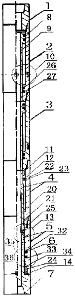
[0029] refer to figure 1 Shown, further illustrate the structure of the present invention. The present invention is composed of an upper joint 1 that can be connected with a drilling tool, two groups of hydraulic pressurization devices 2 and 3, a torque transmission device 4 and a weight-on-bit tracking warning device 5 . The upper end of the hydraulic pressure device 2 is connected to the upper joint 1 through a drill pipe thread, and the lower end is connected to the upper end of the hydraulic pressure device 3 through a drill pipe thread, forming a series connection of two hydraulic pressure devices 2 and 3; The lower end of the hydraulic pressure device 3 is connected with the upper end of the inner square sleeve 21 of the torque transmission device 4 through a drill pipe thread. Torque transmission device 4 is made up of collar 59, retaining ring 11, pressure balance mechanism 12, outer square shaft 20, inner square sleeve 21, sealing ring 22 and 23; The buckle is conne...

Embodiment 2

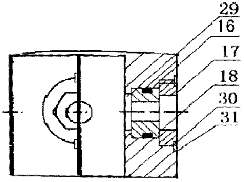
[0033] Embodiment 2 is based on Embodiment 1, further illustrating the structures of the torque transmission device 4 and the weight-on-bit tracker 5 of the present invention. see Figure 4 to Figure 11 As shown, the outer shaft 20 and the central shaft 7 of the torque transmission device 4 and the weight-on-bit tracker 5 in this example are integrated. The inner square sleeve 21 is connected with the sealing cylinder 25 through a drill pipe thread. The outer shaft 20 and the central shaft 7 are installed in the inner square sleeve 21 and the sealing cylinder 25 respectively, and the outer face 41 of the outer square shaft 20 forms a clearance fit with the inner face 46 of the inner square sleeve 21 . The balance mechanism 12 is installed in the annular space formed by the cylindrical surface 40 of the outer square shaft 20 and the inner hole surface 45 of the inner square sleeve 21. The sealing rings 22 and 23 are respectively installed in the sealing rings 56 and 57 of the ...

Embodiment 3

[0035] refer to Figure 1 to Figure 11 As shown, further illustrate the implementation steps of a hydraulic pressurizer:

[0036] In step 101, a hydraulic pressurizer is connected between the drill bit and the drill collar, or between two drill collars, and lowered into the well. At this time, a hydraulic pressurizer is in a stretched state, that is, the lower end surface 62 of the balance mechanism 12 is seated on the inner step 65 of the inner square sleeve 21, and the lower end surface 64 of the retaining ring 11 is seated on the upper end surface 63 of the balance mechanism 12 At the same time, the cemented carbide nozzle 18 of the signal device 13 is facing the steel-bonded alloy ring 24 of the 36 of the liquid discharge mechanism.

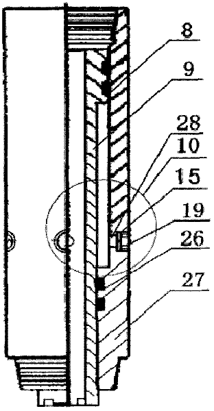
[0037] Step 102 When the mud is circulated, the piston 9 is pushed down to the starting point by the mud pressure, that is, close to the respirator 10 . Part of the mud flows out through the drill bit nozzle, and another part of the mud pas...


PUM


Abstract

The invention relates to a hydraulic pressurizer, belonging to the technical field of slurry circulating equipment of bored wells. The pressurizer at least comprises an upper connector, a hydraulic pressurizing device, a torque transmission device and a bit pressure tracking early-alarming device that is connected with a drill bit. The hydraulic pressurizing device comprises a hydraulic cylinder, a hollow piston and a respirator; the torque transmission device comprises an external square shaft, an internal square sleeve, a retainer ring and a pressure balance mechanism; and the bit pressure tracking early-alarming device comprises a signal device, a seal cylinder, a central shaft, a seal mechanism and a liquid drainage mechanism. The pressurizer is connected between drilling tools. The bit pressure can be accurately applied to the drill bit by using the pressurizer. According to the pressurizer disclosed by the invention, pulse jet stream with sound harmonic resonance can be produced through a labial structure formed by a water course and a drill bit nozzle of the pressurizer, cavitation is induced in relatively static slurry, such that the bottom of a well produces transient low pressure to reduce 'hold-down effect' of a slurry liquid column. When the bit pressure is changed, the bit pressure tracking early-alarming device can send out a signal to indicate operation. The pressurizer has the capabilities of absorbing vibration of drilling tools and prolonging service life of the drill bit. Moreover, the pressurizer has the functions of inclining prevention, angle maintaining and speed acceleration.

Description

technical field [0001] The invention belongs to the technical field of hydraulic or mud circulation drilling equipment. technical background [0002] In the conventional drilling process, the drill bit is directly connected to the lower end of the drilling tool, and the drilling pressure is provided by the weight of the drilling tool. There are many disadvantages in this way: [0003] 1. It is difficult to guarantee the drilling pressure, and it is difficult to control the amount of drilling; the drilling pressure is small and the drilling speed is low; the high drilling pressure affects the life of the drill bit and the life of the drill tool; [0004] 2. During drilling in special strata, due to factors such as stratum, wellbore and operation, there will be drilling vibration. The vibration source comes from the drill bit and drilling tool, which seriously affects the life of the drill bit and drilling tool. Various shock absorbers are designed for this purpose. , but the...

Claims


Application Information

Patent Timeline
IPC IPC(8): E21B17/00E21B44/00E21B21/08
Inventor 刘白杨刘泽灏刘瑞刘泽宇刘哲汐刘大红刘先明张学萍徐瑞鸿
Owner 刘白杨
Why Eureka
Try Eureka