Vehicle-mounted engine controller

A control device and engine technology, applied in engine control, machine/engine, electrical control, etc., can solve the problems of large overcurrent burden of batteries, excessive heat of switching elements, large excitation current, etc., to achieve overcurrent burden reduction and power supply Effect of current averaging and prevention of malfunction

Inactive Publication Date: 2015-05-06
MITSUBISHI ELECTRIC CORP
View PDF6 Cites 0 Cited by
  • Summary
  • Abstract
  • Description
  • Claims
  • Application Information

AI Technical Summary

Problems solved by technology

[0008] The control device of the fuel injection valve disclosed in Patent Document 1 has the following problems: when the engine rotates at a high speed, it is necessary to perform a step-up conversion operation at a high frequency, and the inductive element mounted on the electronic board and the excitation current of the inductive element are controlled. The heat generated in the intermittently driven switching element is too large locally, and when the high-frequency step-up conversion operation is not required during low-speed rotation, the excitation current of the induction element is also large, and the overcurrent burden of the battery when the engine is cold started larger

Method used


Image

  • Vehicle-mounted engine controller
  • Vehicle-mounted engine controller
  • Vehicle-mounted engine controller

Examples


Embodiment approach 1

[0073] (1) Detailed description of the structure

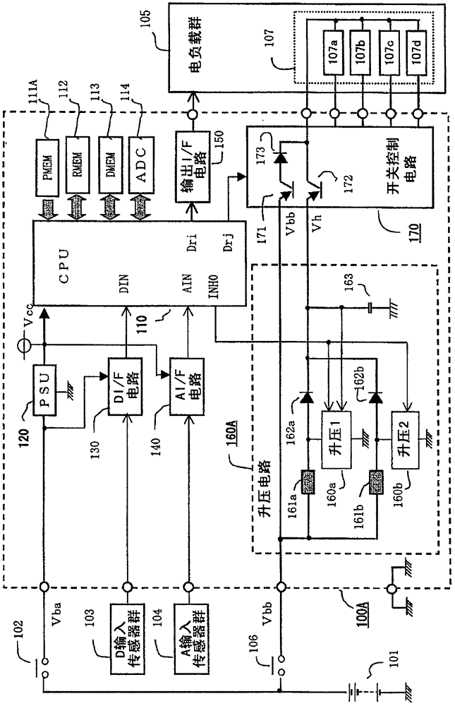
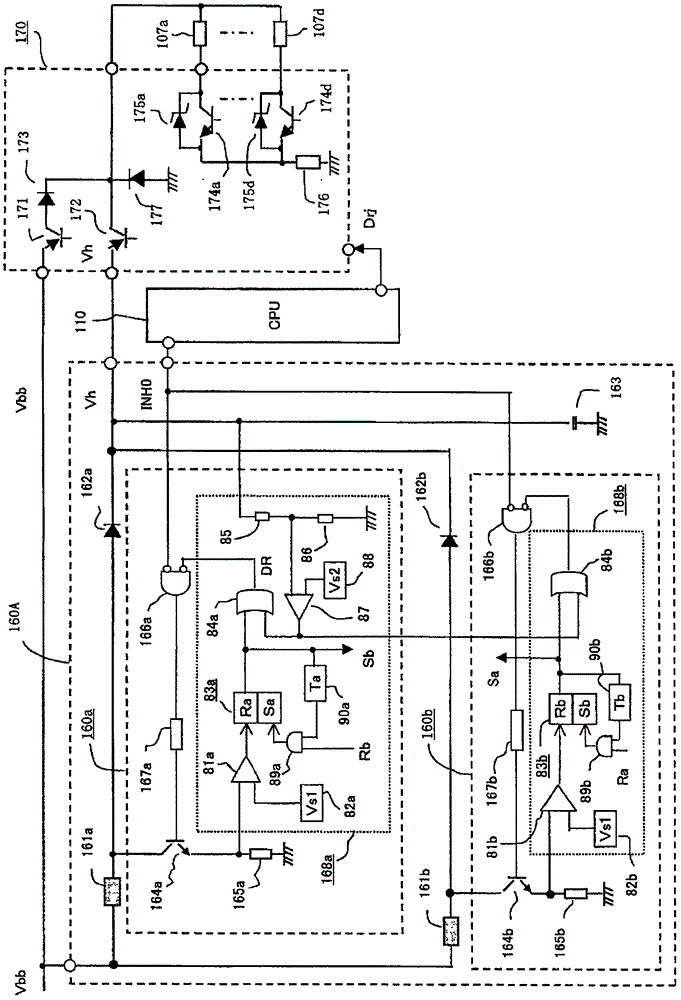
[0074] Hereinafter, the in-vehicle engine control device according to Embodiment 1 of the present invention will be described. figure 1 It is a block diagram showing an overall circuit in the vehicle-mounted engine control device according to Embodiment 1 of the present invention. exist figure 1 Among them, the on-vehicle engine control device 100A is mainly composed of a microprocessor 110, and includes a booster circuit 160A and a switch control circuit for overexcitation control of the electromagnetic coil 107 of the solenoid valve for fuel injection, which is a part of the electric load group 105. circuit 170.

[0075] First, as a component connected to the outside of the vehicle engine control device 100A, the vehicle battery 101 supplies the main power supply voltage Vba to the vehicle engine control device 100A by controlling the power switch 102 . The control power switch 102 is an output contact of an electromagnet...

Embodiment approach 2

[0160] (1) Detailed description of the structure

[0161] Next, an in-vehicle engine control device according to Embodiment 2 of the present invention will be described. Figure 5It is a block diagram showing the overall circuit of the vehicle-mounted engine control device according to Embodiment 2 of the present invention. In the following description, the same as in Embodiment 1 figure 1 The differences will be explained centering on. In addition, the same code|symbol in each figure shows the same or corresponding part.

[0162] exist Figure 5 Among them, the on-vehicle engine control device 100B is mainly composed of a microprocessor 110, and includes a booster circuit 160B for overexcitation control of the electromagnetic coil 107 of the solenoid valve for fuel injection, which is a part of the electric load group 105, and a switch control unit. circuit 170.

[0163] outside the on-vehicle engine control device 100B, and figure 1 Like the device, the vehicle battery...

Embodiment approach 3

[0233] (1) Detailed description of the structure

[0234] Next, an in-vehicle engine control device according to Embodiment 3 of the present invention will be described. Figure 8 It is a block diagram showing the overall circuit of the vehicle-mounted engine control device according to Embodiment 3 of the present invention. Below, based on Figure 8 , with the above figure 1 , Figure 5 The difference between the devices will be explained mainly. In addition, the same code|symbol in each figure shows the same or corresponding part.

[0235] exist Figure 8 Among them, the on-vehicle engine control device 100C is mainly composed of a microprocessor 110, and includes a booster circuit 160C for overexcitation control of the electromagnetic coil 107 of the solenoid valve for fuel injection, which is a part of the electric load group 105, and a switch control unit. circuit 170. on the outside of the vehicle engine control device 100C, and figure 1 Like the device, the vehi...


PUM


Abstract

The system has voltage gain circuit (160A) with loading diodes (162a,162b) that are connected in series to the inductors (161a,161b). A high voltage capacitor (163) is charged by current flowing through the inductors and diodes. The opening / locking control circuit (170) is provided with low-voltage opening / locking unit (171) which is connected between vehicle accumulator (101) and electromagnetic coils (107a-107d). The voltage gain control circuits are charged alternately so that overlapping of the peak values of exciting currents of inductors is avoided. The high voltage opening / locking unit (172) is connected between high voltage capacitor and electromagnetic coils. The selective opening / locking units are connected in series with the electromagnetic coils. The line timings and spacer periods of the selective opening / locking units are adjusted by a microprocessor (110). The voltage gain control circuits are charged alternatively so that overlapping of the peak values of exciting currents of inductors is avoided. The charging timing of the voltage gain control circuits is set in the timing circuits, based on predetermined time. The back current prevention diode (173) is connected in series with low-voltage opening / locking apparatus.

Description

technical field [0001] The present invention relates to a vehicle-mounted engine control device, in order to drive a solenoid valve for fuel injection of an internal combustion engine at a high speed, a high voltage obtained after being boosted by a vehicle-mounted battery is instantly supplied to an electromagnetic coil for driving the solenoid valve, and the voltage of the vehicle-mounted battery is used to perform the operation. The valve opening keeps the control, especially related to the structure of the improved booster circuit. Background technique [0002] Fuel injection control that sequentially selects and sets the valve opening timing and valve opening period by a microprocessor that operates based on a crank angle sensor for driving a plurality of solenoid coils for driving a fuel injection solenoid valve provided in each cylinder of a multi-cylinder engine In the device, various improvements have been made to the booster circuit for rapid valve opening by overv...

Claims


Application Information

Patent Timeline
Patent Type & Authority Patents(China)
IPC IPC(8): F02D41/04F02D41/20F02D41/26
CPCF02D41/20F02D41/062F02D2041/2006F02D2041/201F02D2200/101
Inventor 木村友博西田充孝西泽理
Owner MITSUBISHI ELECTRIC CORP
Why Eureka
Try Eureka