
Equipment for producing reflection film with microprism array structure by using annular strip die

A strip mold and array structure technology, applied in optics, optical components, instruments, etc., can solve problems such as unfavorable reflective film processing and use, limited application range of reflective film, environmental impact, etc., to facilitate subsequent processing and use, The effect of low production cost and environmental protection in the production process

Active Publication Date: 2013-10-23
ZHEJIANG DAOMING OPTOELECTRONICS TECH
View PDF6 Cites 0 Cited by
  • Summary
  • Abstract
  • Description
  • Claims
  • Application Information

AI Technical Summary

Problems solved by technology

[0006] Although the microprism structure formed by the above method and equipment has excellent hardness, scratch resistance, heat resistance, solvent resistance, and good product consistency, due to the relatively few types of photosensitive resins and special properties, the general price are very high; and the photosensitive resin will have certain solvent emissions during the coating and drying process. When UV light irradiates the photosensitive resin to cure it, it will also cause part of the monomers in the photosensitive resin to escape and be exposed to the air. In addition, after the photosensitive resin is cured, the molecules are cross-linked into a network, the surface is dense, and the polarity is very low. Although a layer of metal reflection can be deposited on the surface of the microprism layer, but it is difficult to seal a layer of base film on the surface of one side of the microprism by using existing welding technologies such as ultrasonic waves, high frequency waves or hot melt, so it is not conducive to the subsequent processing and use of the reflective film, and the application range of the reflective film is also limited. will be restricted

Method used


Image

  • Equipment for producing reflection film with microprism array structure by using annular strip die
  • Equipment for producing reflection film with microprism array structure by using annular strip die
  • Equipment for producing reflection film with microprism array structure by using annular strip die

Examples


Embodiment 1

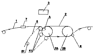
[0049] Such as figure 1 and Figure 7 As shown, the equipment for producing reflective film with a microprism array structure is produced with an annular belt mold, including an annular belt mold 2, a molding device and a coating device 3 of a hot-melt resin 12, and the annular belt mold 2 has an inner surface 21 And an outer surface 22, the outer surface 22 has a concave continuous microprism array structure 23, the ring-shaped belt mold 2 is installed on the support roller 2A and the support roller 2B arranged in parallel, forming a closed loop reciprocating motion, two The support rolls are all hollow rigid rolls, made of steel, copper or iron materials, the inside of the support roll 2A near the entrance of the resin film 1 passes through the cooling medium, and away from the support roll 2B at the entrance of the resin film 1 The inside passes through the cooling medium, and the outer surface of one end of the support roll 2B away from the entrance of the resin film 1 on...

Embodiment 2

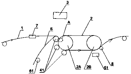
[0061] Such as figure 2 and Figure 7 As shown, the equipment for producing reflective film with a microprism array structure is produced with an annular belt mold, including an annular belt mold 2, a molding device and a coating device 3 of a hot-melt resin 12, and the annular belt mold 2 has an inner surface 21 And an outer surface 22, the outer surface 22 has a concave continuous microprism array structure 23, the ring-shaped belt mold 2 is installed on the support roller 2A and the support roller 2B arranged in parallel, forming a closed loop reciprocating motion, two The support rolls are all hollow rigid rolls, made of steel, copper or iron materials, and the inside of the support roll 2A near the entrance of the resin film 1 passes through the cooling medium. One end outer surface of the support roll 2B at the entrance of the ester film 1 is provided with an external cold air spray device 51, and after the cold air spray device 51 cools the hot melt resin 12, one side...

Embodiment 3

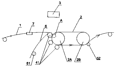
[0073] Such as image 3 and Figure 7 As shown, the equipment for producing reflective film with a microprism array structure is produced with an annular belt mold, including an annular belt mold 2, a molding device and a coating device 3 of a hot-melt resin 12, and the annular belt mold 2 has an inner surface 21 And an outer surface 22, the outer surface 22 has a concave continuous microprism array structure 23, the ring-shaped belt mold 2 is installed on the support roller 2A and the support roller 2B arranged in parallel, forming a closed loop reciprocating motion, two The support rolls are all hollow rigid rolls, made of steel, copper or iron materials, and the inside of the support roll 2A near the entrance of the resin film 1 passes through the cooling medium. One end outer surface of the support roll 2B at the entrance of the ester film 1 is provided with an external hollow rigid roll 52 that passes through the cooling medium, made of steel, copper or iron material, as...


PUM


Abstract

The invention relates to equipment for producing reflective film with microprism array structure by using an annular belt mold. In the prior art, the use of photosensitive resin as a microprism molding material has defects such as narrow selection range, high production cost, poor follow-up processing performance and narrow application range. The invention comprises a ring-shaped belt mold, a hot-melt resin coating device and a molding device. The ring-shaped belt mold has an inner surface and an outer surface, and the outer surface has a concave continuous microprism array structure, and the coating of the hot-melt resin The device applies hot-melt resin to one side of the resin film, and the side surface of the resin film is close to the outer surface of the ring-shaped belt mold, and the hot-melt resin is filled with the concave microprism array structure by molding Clearance. The invention uses hot-melt resin to form the microprism array structure, and the subsequent processing performance of the made reflective film is more excellent and the application range is wider; the equipment does not need drying and UV curing devices, the processing cost is low, and the production speed can be significantly improved. The process is more environmentally friendly.

Description

technical field [0001] The invention relates to a device for producing a reflective film, in particular to a device for producing a reflective film with a microprism array structure. Background technique [0002] Reflective materials with a microprism array structure are more and more widely used in various road traffic safety facilities, vehicle passive safety protection devices, signs and personal safety protection products due to their excellent retroreflective properties. [0003] The invention patent application with the publication date of October 21, 2009, the publication number CN101561523, and the name "Production method of reflective film with microprism array structure" discloses a production of reflective film using photosensitive resin to form microprisms. The production method includes the main steps of: coating a photosensitive resin on a resin film, drying, heating and molding, and then rapidly curing by UV light irradiation, so that the resin film coated wit...

Claims


Application Information

Patent Timeline
Patent Type & Authority Patents(China)
IPC IPC(8): G02B5/124
Inventor 王宏蓝庆东吴伟斌胡智彪胡智雄
Owner ZHEJIANG DAOMING OPTOELECTRONICS TECH
Learn More