Phase plate for wave-front coding imaging technology

A technology of wavefront encoding and phase plate, which is applied in optics, instruments, optical components, etc., can solve the problem of reducing dependence and achieve the effect of reducing sensitivity

Inactive Publication Date: 2011-11-16
XI'AN INST OF OPTICS & FINE MECHANICS - CHINESE ACAD OF SCI
View PDF1 Cites 7 Cited by
  • Summary
  • Abstract
  • Description
  • Claims
  • Application Information

AI Technical Summary

Problems solved by technology

[0010] Obviously, the modulus of the defocused OTF at this time, that is, the MTF has nothing to do with the defocused wave aberration coefficient, that is to say, the cubic phase plate can make the system MTF insensitive to defocus; although the phase part of the OTF is related to the defocus parameter W 20 related, but as long as the modulation factor α increases, its effect on W 20 will be significantly less dependent on

Method used


Image

  • Phase plate for wave-front coding imaging technology
  • Phase plate for wave-front coding imaging technology
  • Phase plate for wave-front coding imaging technology

Examples


Embodiment Construction

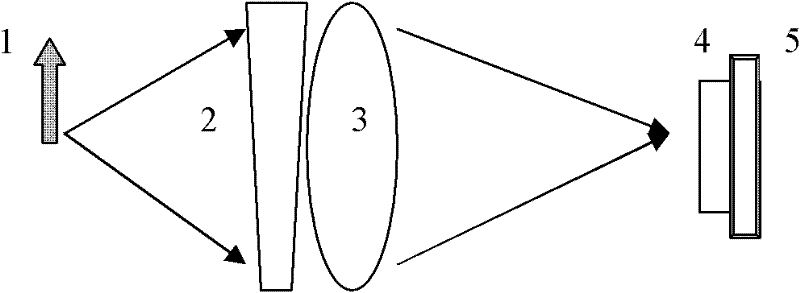
[0035] The phase plate used in the wavefront encoding imaging system involved in the present invention has a phase distribution function formed by superimposing a third-order power function and a sine function, or an exponential function and a sine function, or a logarithmic function and a sine function.

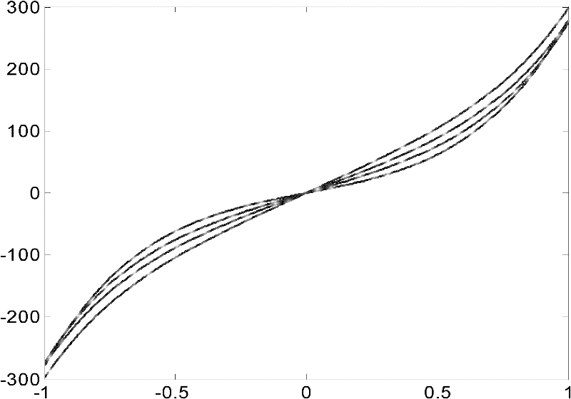
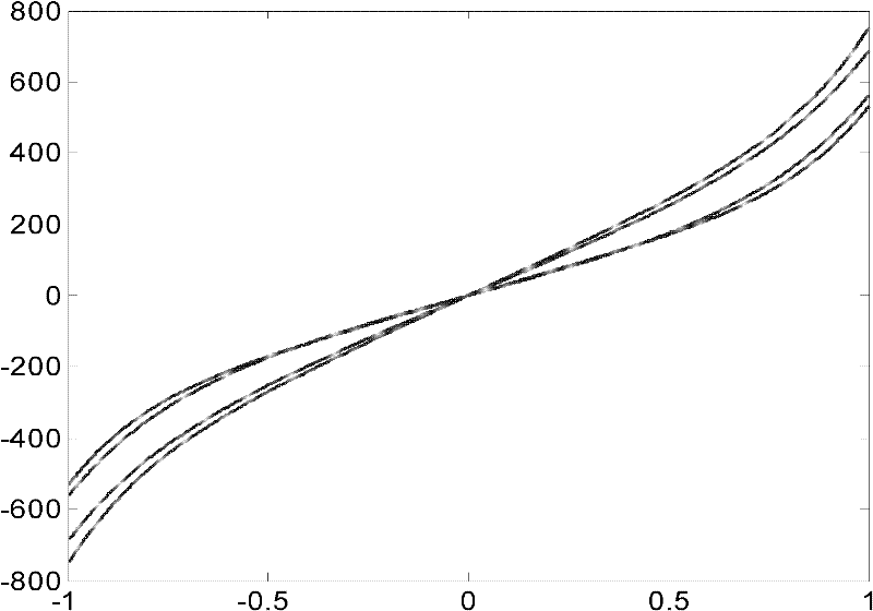
[0036] When its phase distribution function is formed by the superposition of a third-order power function and a sine function, its one-dimensional function expression is:

[0037] f 1 (x)=α·x 3 +β sin(ω x)

[0038] In the formula, α, β, ω are the parameters of the phase distribution function of the phase plate, and x is the normalized coordinate, and its value range is [-1, 1].

[0039] After using the simulated annealing algorithm to perform multi-parameter optimization on the phase plate above, the optimal surface parameters under different constraints corresponding to the phase plate can be obtained, as shown in Table 1, and the one-dimensional phase parameters corresp...


PUM


Abstract

The invention relates to a phase plate for a wave-front coding imaging system. A surface type phase distribution function of the phase plate is formed by overlapping a three-order power function with a sine function or overlapping an exponential function with the sine function or overlapping a logarithmic function with the sine function. Corresponding one-dimensional phase distribution functions of the phase plate are shown as follows: f1(x)=alpha*x<3>+beta*sin(omega*x), f2(x)=rho*x*exp(alpha*x<2>)+beta*sin(omega*x), and f3(x)=sgn(x)*{rho*x<2>*[1n(an absolute value of x)+alpha]}+beta*sin(omega*x), wherein in the formulae, alpha, beta, omega and rho are parameters of the phase distribution functions of the phase plate; sgn is a symbolic function, when x is more than 0, the value of the symbolic function is positive 1, and when x is less than 0, the value of the symbolic function is negative 1; and x is a normalized coordinate which is at a value interval between negative 1 and positive 1. The phase plate for the wave-front coding imaging technology has the advantage that: the non-sensibility of a wave-front coding imaging system on defocusing can be further improved, so for each phase plate, intermediate fuzzy images at all defocusing positions can be effectively restored by using only one digital filter.

Description

technical field [0001] The present invention relates to a composite form phase plate for wavefront encoding imaging technology. Background technique [0002] The depth of field of extended optical systems has always been a hotspot in academic research. Since the mid-1980s, although various methods have been proposed for depth of field expansion, it was not until Dr. Dowski and Professor Cathey of the University of Colorado in the United States proposed the wavefront in 1995. After the concept of coding, the extension of depth of field had a real breakthrough. [0003] Taking the one-dimensional optical system as an example, its defocus optical transfer function OTF can be obtained through the autocorrelation operation of the generalized pupil function, as follows: [0004] H ( u , W 20 ) = 1 2 · ...

Claims


Application Information

Patent Timeline
Patent Type & Authority Applications(China)
IPC IPC(8): G02B5/30G02B27/00
Inventor 赵惠易红伟李英才雷广智贺天兵
Owner XI'AN INST OF OPTICS & FINE MECHANICS - CHINESE ACAD OF SCI
Why Eureka
Try Eureka