Filling pile coring method and combined concrete coring device

A coring device and cast-in-situ pile technology, which is applied to drilling equipment and methods, sheet pile walls, earthwork drilling and mining, etc., can solve the difficulty of pouring construction steel bars, high storage and maintenance costs, unfavorable small construction sites, etc. problem, to achieve the effect of simple structure, convenient combination and low cost

Inactive Publication Date: 2013-04-24
常华北
View PDF5 Cites 0 Cited by
  • Summary
  • Abstract
  • Description
  • Claims
  • Application Information

AI Technical Summary

Problems solved by technology

The cost of using large-scale drilling equipment is high, and it is difficult to move and drive into the construction site, thereby reducing work efficiency. In addition, large-scale drilling equipment also has high storage and maintenance costs, which is not conducive to the needs of small construction sites.
In view of the shortcomings of large-scale drilling equipment, the current coring method suitable for small construction sites is to manually use pneumatic picks to gradually crush the cast-in-situ piles from top to bottom. Workers take turns to work, and the work efficiency is very low, but the groundwater has been demolished, and containment and drainage need to be taken, which further reduces the work efficiency
In addition, in the prior art, after taking out the demolished piles, it is still necessary to continue to contain the pile foundation at the lower section to form new cast-in-place piles. There is a certain probability that there will be a broken section

Method used


Image

  • Filling pile coring method and combined concrete coring device
  • Filling pile coring method and combined concrete coring device
  • Filling pile coring method and combined concrete coring device

Examples


Embodiment 1

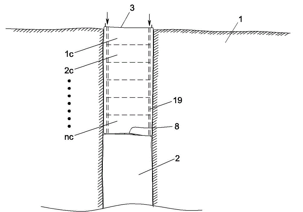
[0027] Embodiment one: see figure 1 The cast-in-place pile is a combination of concrete and circular steel reinforcement layer. The underground pile foundation is formed by drilling a well in the soil layer 1 and pouring concrete. During the pouring and forming process of the concrete cast-in-place pile, some cast-in-place piles may fail to be poured somewhere in the middle Like or form a broken pile, it cannot be used normally. The broken position 8 is judged by echo monitoring, the upper section 3 (broken section) of the broken pile is cored, and the integrated concrete pouring pile is continuously poured on the basis of the lower section 2 .

[0028] This embodiment provides a method for coring cast-in-situ piles. Select a suitable annular drilling tool according to the diameter of the broken pile. For example, for a broken pile with a diameter of D0, the diameter of the annular reinforcement layer is D2. Inside the annular reinforcement layer, use An annular hollow drilli...

Embodiment 2

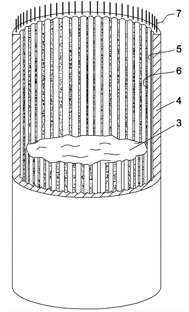
[0032] Embodiment two: see figure 2 and image 3 , the content is basically the same as that of Embodiment 1, and the similarities will not be repeated. The difference is: the annular drilling tool used in the inner side of the annular reinforcement layer 7, the annular drilling tool is evenly distributed with a plurality of independent working drills on the annular surface. The lower end of each drill body has a drill bit respectively, and a series of drill holes are combined to form a circular drill hole. After the inner core 3 is smashed and cleaned, the inner wall of the cylindrical concrete shell 4 forms a rough surface with alternating convex and concave. Number 6 is the broken and protruding rough surface, and number 5 is the concave surface formed by drilling.

Embodiment 3

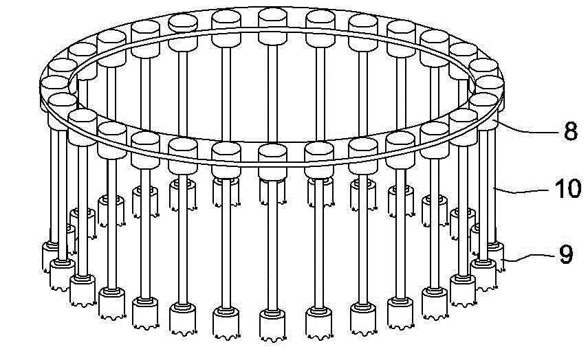
[0033] Embodiment three: see Figure 4 , Figure 5 and Figure 9 , a combined concrete coring device suitable for the cast-in-situ pile coring method described in Embodiment 2, is that the motor parts of a plurality of drill bodies are sequentially hinged to form a ring-shaped combined drilling tool. Each drill body includes a motor part 8 , a drill rod 9 and a drill bit 10 . Connecting lugs 11 are horizontally fixed on the casing of the motor part of each drill body, and shaft holes 13 are respectively provided on each connecting lug, and the connecting lugs of two adjacent drill bodies are matched and nested together, and pin shafts 12 are installed in the shaft holes. . The drill bodies of the combined drilling tool are fixed to each other. Its fixing method is by a fixed sleeve 16, and near the outer edge of this fixed sleeve, mounting holes 17 are evenly distributed, and the motor part shells of each drill bit are matched and fitted and fixed in each mounting hole.


PUM


Abstract

The present invention relates to a cast-in-situ pile coring method and a combined concrete coring device. The coring method is to make circular drilling in sections from top to bottom along the upper end surface of the broken pile, clean the columnar inner core and finally form a circular reinforcing bar layer. The cylindrical concrete shell; the coring device is composed of multiple drill bodies and their motor parts are sequentially hinged to form a ring-shaped combined drilling tool. Utilizing the method and device of the present invention to finally form the inner wall of the shell due to drilling to form a convex-convex rough surface, almost no further processing is required to directly pour concrete, and new cast-in-situ piles can be formed at one time, so that coring and coring The final pouring has achieved the effect of saving time and labor. The coring device can realize the change of the diameter of the entire drilling tool by adjusting the number of drill bodies, so that it is suitable for demolition piles of different diameters. Moreover, the present invention does not need to consider and deal with underground water seepage and sludge treatment, thereby further improving construction efficiency.

Description

technical field [0001] The invention relates to a coring technology for concrete pouring piles, in particular to a coring method for pouring piles and a combined concrete coring device. Background technique [0002] Due to the unavoidable partial pouring or broken piles in the pouring construction process of concrete pouring piles, once similar situations occur, secondary pouring must be carried out, and the upper part must be taken out in order to achieve the new pouring conditions , On the foundation of the lower section, continue pouring to form an integrated concrete pouring pile. At present, the method of coring cast-in-situ piles is usually to use large-scale drilling equipment or to break manually with a pneumatic pick. The cost of using large-scale drilling equipment is very high, the movement is difficult, and it is difficult to drive into the construction site, thereby reducing work efficiency, and the storage and maintenance costs of large-scale drilling equipmen...

Claims


Application Information

Patent Timeline
Patent Type & Authority Patents(China)
IPC IPC(8): E21B10/06E02D5/64E21B3/00E21B3/02
Inventor 马东旭杨志兵李卫兵殷川唐海燕李有贵金志宏贺志杉王刚张艳军常天冰常新伟常华北
Owner 常华北
Why Eureka
Try Eureka