
Biomass low-nitrogen direct combustion boiler

A biomass and low-nitrogen technology, applied in the direction of combustion methods, combustion equipment, solid fuel combustion, etc., can solve the problems of combustible gas not easy to burn out, low ignition point, high volatile content of biomass fuel, etc., to avoid gas incompleteness Combustion loss, suppression of NOx generation, and improvement of boiler thermal efficiency

Active Publication Date: 2011-11-23
山东知周环境科技有限公司
View PDF15 Cites 17 Cited by
  • Summary
  • Abstract
  • Description
  • Claims
  • Application Information

AI Technical Summary

Problems solved by technology

However, most of the biomass boilers currently on the market are simply transformed from coal-fired boilers, or directly use coal-fired boilers (such as: Chinese patent applications 200710049037.3, 200810137245.3, 201010151608.6), which are difficult to take advantage of biomass fuels and are not suitable for Biomass fuel has high volatile content, low ignition point, combustible gas is not easy to burn out and other combustion characteristics, low combustion efficiency, high exhaust temperature, and low thermal efficiency
In addition, the nitrogen oxide emissions of biomass boilers are relatively high, and under certain conditions, nitric acid rain can be formed, which has great damage to the ecological environment.
The inventions of Chinese patent applications 200910187815.4 and 201020528853.X adopt secondary air distribution or use fluidization technology to assist combustion, but they ignore the impact of NOx produced by fuel combustion on the environment and the comprehensive utilization efficiency of energy. room for development

Method used


Image

  • Biomass low-nitrogen direct combustion boiler
  • Biomass low-nitrogen direct combustion boiler
  • Biomass low-nitrogen direct combustion boiler

Examples


Embodiment Construction

[0028] The present invention will be further described below in conjunction with the accompanying drawings and embodiments.

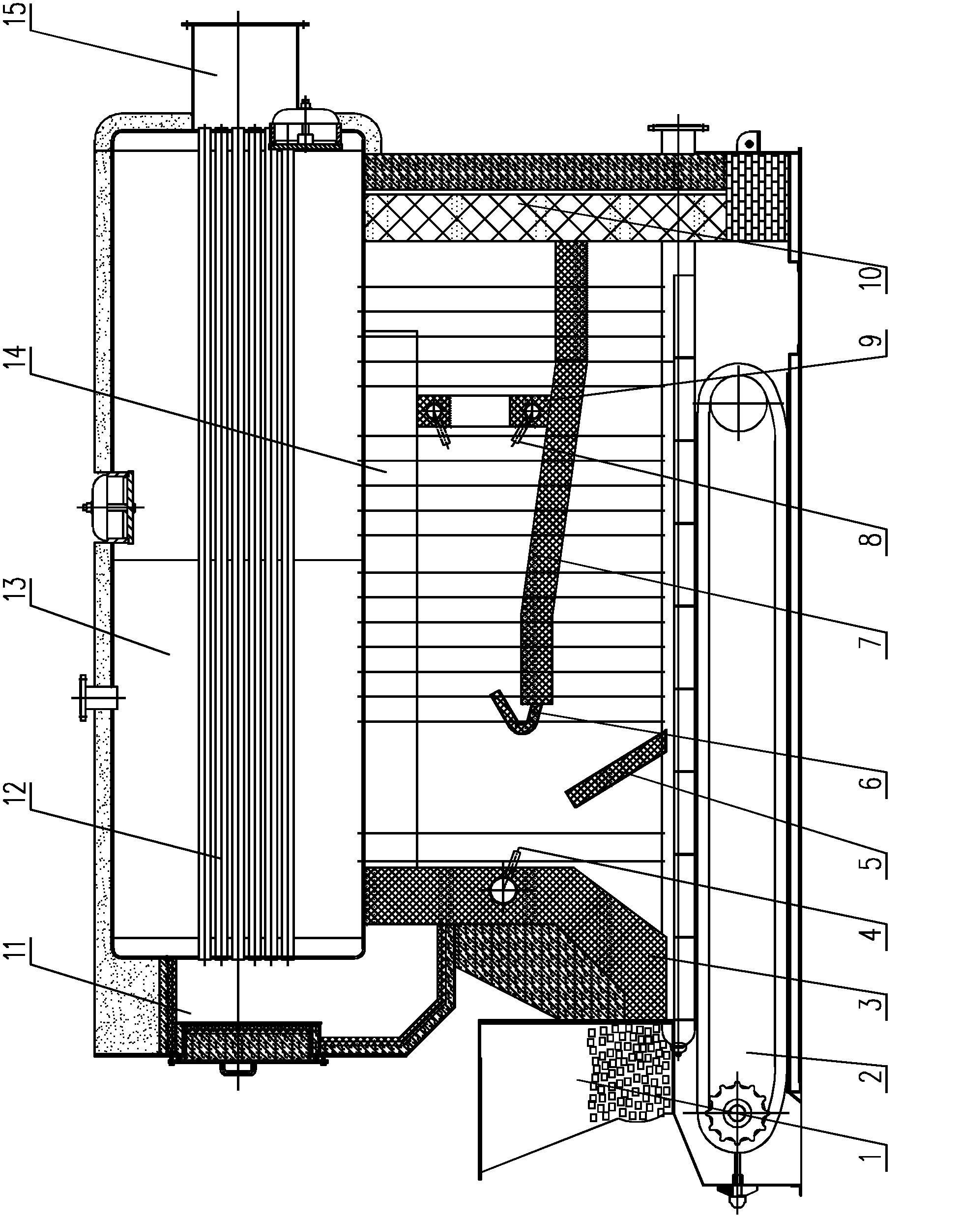
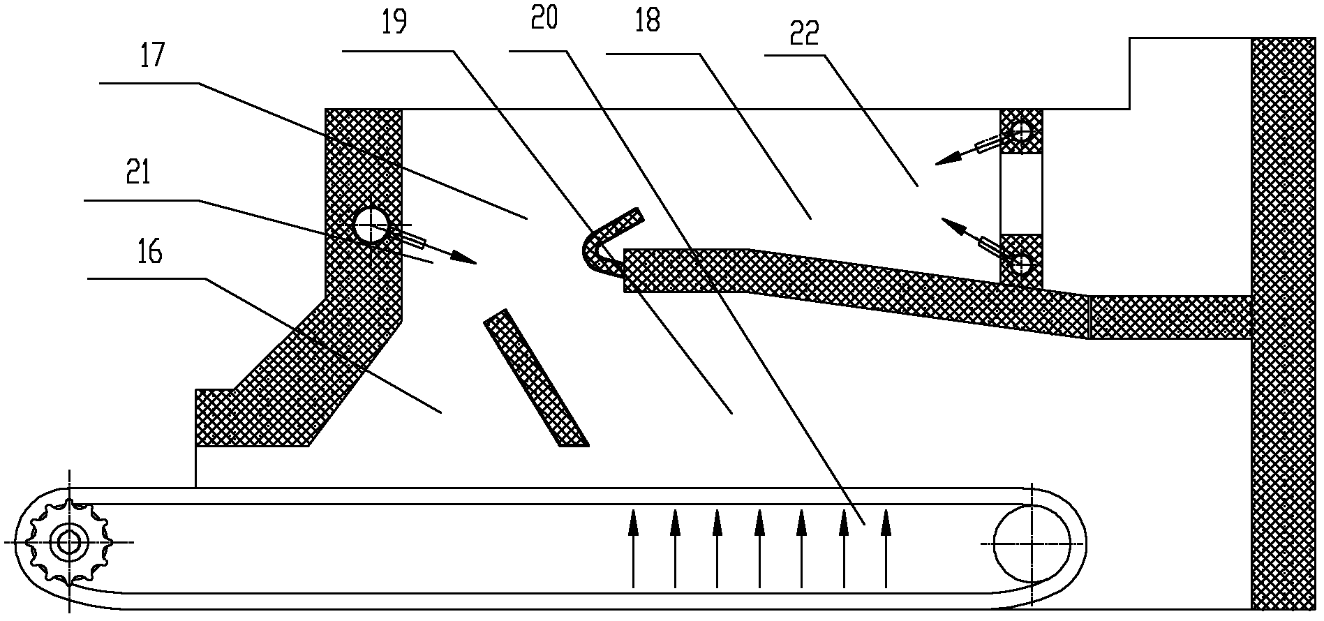
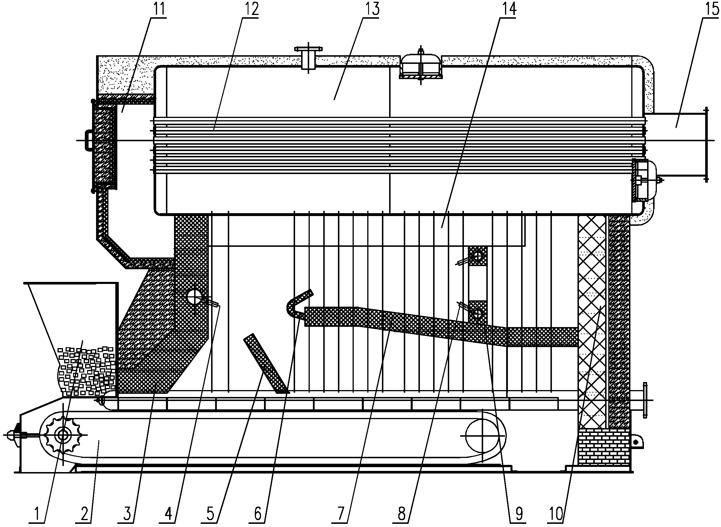
[0029] Such as figure 1 , 2 As shown, a biomass low-nitrogen direct-fired boiler includes a furnace. A boiler body 13 is arranged on the upper part of the furnace. The front and rear ends of 13 are respectively provided with a front smoke box 11 and a rear smoke box 15. The cavity of the furnace is surrounded by the front arch 3, the rear wall 10, the boiler body 13 and the chain grate 2. (The partition arch 5 is used to form the reaction microenvironment of the high-temperature pyrolysis zone, block the primary air distribution, and play the role of spreading the fuel), the rear arch 7, the airfoil flue 14 and the smoke separation wall 9, and the front end of the rear arch 7 There is a flue gas deflector 6, the smoke partition wall 9 is arranged on the upper part of the rear arch 7, the airfoil flue 14 is arranged on the upper area of ​​the furnace c...


PUM


Abstract

The invention relates to a biomass low-nitrogen direct combustion boiler, comprising a hearth, wherein a boiler body is arranged on the upper part of the hearth, a hopper is arranged at a feeding port in the front of the hearth, a chain grate is arranged on the lower part of the hearth, a front smoke box and a rear smoke box are arranged at the front and the rear ends of the boiler body respectively, an isolating arch, a rear arch, a wing-shaped flue and a flue-gas-isolating wall are arranged inside a hearth cavity, a flue gas guide plate is arranged at the front end of the rear arch, the flue-gas-isolating wall is arranged on the upper part of the rear arch, a secondary air device is arranged on the front arch, and a tertiary air device is arranged on the flue-gas-isolating wall; and the hearth cavity is internally divided into a pyrolysis region, a layer combustion region, a re-combustion reduction region and a gasification combustion region. According to the invention, in accordance with the components and the combustion features of biomass fuel, efficient combustion of the fuel is realized by adopting the technologies of layer combustion and gasification coupling combustion, and ultralow emission of nitrogen oxides is realized by adopting the technologies of hierarchical air distribution, semi-coke reduction and re-combustion of pyrolysis products, therefore, the biomass boiler becomes a real energy-saving and environment-friendly product.

Description

technical field [0001] The invention relates to a biomass boiler, in particular to a biomass low-nitrogen direct-fired boiler. Background technique [0002] At present, under the dual conditions that the country attaches great importance to the development of biomass energy and restricts coal burning, biomass boilers are gradually favored due to policy support and superior environmental protection and economic performance, and have become an important product to replace coal-fired and oil-fired gas-fired boilers. However, most of the biomass boilers currently on the market are simply transformed from coal-fired boilers, or directly use coal-fired boilers (such as: Chinese patent applications 200710049037.3, 200810137245.3, 201010151608.6), which are difficult to take advantage of biomass fuels and are not suitable for Biomass fuel has combustion characteristics such as high volatile content, low ignition point, and non-combustible gas, low combustion efficiency, high exhaust...

Claims


Application Information

Patent Timeline
IPC IPC(8): F23B90/06F23L1/02F23L9/00
Inventor 张兆玲李景东闫永秀强宁刘桂才刘艳涛景元琢董磊郭飞强
Owner 山东知周环境科技有限公司
Learn More