Shale oil hydrogenation process
A process method, shale oil technology, applied in refining to remove heteroatoms, etc., can solve the problems of increasing ammonia adsorption, low yield of generated oil, increasing post-treatment process, etc.
- Summary
- Abstract
- Description
- Claims
- Application Information
AI Technical Summary
Problems solved by technology
Method used
Image
Examples
Embodiment 1
[0016] Fushun shale oil at 180-380°C was used as the test sample, and its properties are shown in Table 1.
[0017] Table 1 Properties of 180~380℃ distillate oil
[0018] C / %
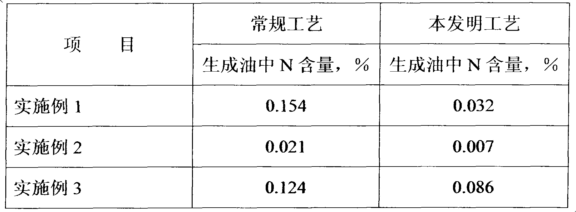
[0019] The hydrofining catalyst is FF-26, at a reaction temperature of 360°C, a reaction pressure of 8.0MPa, and a volumetric space velocity of 0.8h -1 , under the condition of hydrogen-to-oil ratio 300:1, the conventional process (feedstock oil and hydrogen pass through the catalyst bed in parallel from top to bottom) and the countercurrent process were used for comparative experiments, and the results are shown in Table 4.
Embodiment 2
[0021] The whole fraction of Fushun shale oil was used as the test sample, and its properties are shown in Table 2.
[0022] Table 2 Properties of whole fractions
[0023] C / %
[0024] There are two layers of hydrofining catalyst bed, the catalyst in the upper part of the reactor is R-FF-26, the catalyst in the lower part of the reactor is FF-26, and the volume ratio of R-FF-26 and FF-26 is 50:50. At a reaction temperature of 390°C, a reaction pressure of 15.0MPa, and a volumetric space velocity of 0.6h -1 , under the condition of hydrogen-to-oil ratio of 800:1, the content of hydrogen sulfide in the hydrogen entering the reactor was 700 μL / L. The conventional process and the countercurrent process were used for comparative experiments, and the results are shown in Table 4. In addition, in this embodiment, since hydrogen sulfide is added to the hydrogen entering the reactor, the catalyst can maintain good activity and stability.
Embodiment 3
[0026] Fushun shale oil at 380-520°C was used as the test sample, and its properties are shown in Table 3.
[0027] Table 3 Properties of 380~520℃ distillate oil
[0028] C / %
85.63
H / %
11.75
S / %
0.45
N / %
1.0675
[0029] There are two layers of hydrogenation catalyst bed, the catalyst in the upper part of the reactor is R-FF-26, the catalyst in the lower part of the reactor is FF-26, and the volume ratio of R-FF-26 and FF-26 is 30:70. At a reaction temperature of 420°C, a reaction pressure of 10.0MPa, and a volumetric space velocity of 1.0h -1 , under the condition of hydrogen-to-oil ratio of 500:1, the content of hydrogen sulfide in the hydrogen entering the reactor was 100 μL / L. The conventional process and the countercurrent process were used for comparative experiments, and the results are shown in Table 4. In addition, in this embodiment, since hydrogen sulfide is added to the hydrogen entering the reac...
PUM
 Abstract
Description
Claims
Application Information
 - R&D
- Intellectual Property
- Life Sciences
- Materials
- Tech Scout
- Unparalleled Data Quality
- Higher Quality Content
- 60% Fewer Hallucinations
Browse by: Latest US Patents, China's latest patents, Technical Efficacy Thesaurus, Application Domain, Technology Topic, Popular Technical Reports.
© 2025 PatSnap. All rights reserved.Legal|Privacy policy|Modern Slavery Act Transparency Statement|Sitemap|About US| Contact US: help@patsnap.com

