Beam-to-column connectors for construction

A beam-column connection and construction technology, applied in the direction of building components, buildings, building structures, etc., can solve the problems of high labor intensity, large waste of construction raw materials, and increase the difficulty of installation, so as to solve the pollution of the surrounding environment and reduce construction waste , the effect of reducing labor intensity

Inactive Publication Date: 2011-11-30
杨东佐
View PDF10 Cites 14 Cited by
  • Summary
  • Abstract
  • Description
  • Claims
  • Application Information

AI Technical Summary

Problems solved by technology

[0002] Existing cement brick mix, reinforced concrete house building and construction method thereof, owing to need to draw frame, cast concrete etc. with steel bar at the construction site, there is following shortcoming: the one is that its upright column pours and builds earlier, pours on upright column again Concrete floors are built, and the connection between the cement floor and the columns is mainly based on the steel bars on the columns and the cement floor. Since the columns and the cement floor are poured twice, the construction period is long, the labor intensity is high, the pollution is large, and the noise is large. The waste of construction raw materials is large; the second is that the relationship between two cement solids is only the bearing relationship of mechanical loads, and it is impossible to establish a truly integrated internal relationship, which has poor safety, poor earthquake resistance, and short service life; third, it is necessary to use cement, Wood and other building materials destroy ecology; Fourth, when houses are demolished, building materials cannot be reused, resulting in waste of resources and a large amount of construction waste that is difficult to handle; Fourth, due to the heavy weight of the frame structure of traditional cement buildings (high-rise buildings), The mechanical load of the foundation is very large. Once an earthquake shakes, the whole building becomes very fragile and dangerous, which is not conducive to earthquake resistance.
Second, there are many bolts and other fastening connections or welding connections on site, which will increase the difficulty of installation, reduce installation efficiency, and result in high labor and time costs for on-site construction.
The third is that the traditional building steel structure frame beams and columns or beams and beams are connected by bolt fastening or welding, and the respective connection ends must be designed and processed for matching connections. When standard profiles are used for beams or columns , the connecting ends must be designed and processed separately. When beams or columns do not use standard profiles, they need to be specially manufactured. Both methods cannot achieve ma

Method used


Image

  • Beam-to-column connectors for construction
  • Beam-to-column connectors for construction
  • Beam-to-column connectors for construction

Examples


Embodiment 1

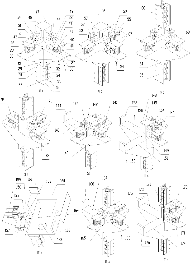
[0088] Such as figure 1 As shown, the beam-column connector, which is a top-level beam-column connector, includes an integral beam-column connector body 25, and a lower column plug connector 26 that needs to be inserted and fixed with the end of the column perpendicular to the horizontal plane. Two cross beams that are perpendicular to each other and directly support parallel to the horizontal plane, a horizontal support joint 27 and a horizontal support joint 28 fixedly connected to the ends of the cross beam.

[0089] Below the beam-column connector body 25 is provided a column-supported horizontal plane 29 directly supported by the column. The lower column plug connector 26 includes two symmetrical U-shaped blocks 30 and U-shaped blocks 31 that extend vertically downward from a horizontal plane 29 supported by the column, with openings facing both sides, and horizontally side by side. The bottom plane of the U-shaped groove of the U-shaped block 31 is provided with a round tab...

Embodiment 2

[0093] Such as figure 1 As shown, the difference from Embodiment 1 is that there are three horizontal support joints, namely horizontal support joint 53, horizontal support joint 54, horizontal support joint 55, horizontal support joint 53, horizontal support joint 54, and horizontal support joint 55 are mutually perpendicular , Into a T shape. The beam-column connector includes an outer side surface 56 without support joints, a horizontal side baffle positioning groove 58 communicating with the outer side surface 56 and the cross beam end face 57 of the horizontal support joint 53, and the outer side surface 56 and the horizontal support joint A horizontal side baffle positioning groove (not shown) connected with the end face of the beam 55 and the resisting surface 59 is connected.

Embodiment 3

[0095] Such as image 3 As shown, the beam-column connector includes an integral beam-column connector body 64, and a lower column protruding vertically downward from the bottom of the beam-column connector body 64 needs to be inserted and fixed to the end of the column in the vertical horizontal direction. The plug connector 65 and an upper column plug connector 66 projecting vertically upward from the top of the beam-column connector body 64, two perpendicular to each other, directly supporting the beam parallel to the horizontal plane, and a horizontal support connector 67 connected and fixed to the end of the beam , Horizontal support joint 68.

[0096] The structures of the lower column plug connector 65, the horizontal support connector 67, and the horizontal support connector 68 are the same as the first embodiment. The upper column plug connector 66 and the lower column plug connector 65 are horizontally symmetrical with respect to their central positions.


PUM


Abstract

The invention discloses a beam column connecting piece used for building. The beam column connecting piece comprises a beam column connecting piece body, an upright post connection-peg and a horizontal supporting joint, wherein the beam column connecting piece body is formed integrally; the beam column connecting piece body is arranged on the upright post connection-peg convexly along the vertical direction, and the beam column connecting piece body is arranged on the horizontal supporting joint convexly along the horizontal direction; the beam column connecting piece comprises an outside surface and a horizontal side baffle plate positioning groove, wherein the outside surface is not provided with the horizontal supporting joint; the horizontal side baffle plate positioning groove is communicated with the outside surface and a beam end surface resisting surface; circular platforms are arranged on the top surface of the side baffle plate positioning groove; reinforcing ribs are connected among the circular platforms; and threaded through holes are reserved in the circular platforms. The beam column connecting piece used for building has the advantages that: L-shaped side baffle plates are convenient to install; the L-shaped side baffle plates and the beam column connecting pieces form a baffle wall of which the periphery is in end-to-end connection; the L-shaped side baffle plates, floor slab supporting templates and the like form accommodation space for casting cement floor slabs, so that cement concrete is convenient to cast to form the floor slabs parallel to a horizontal plane; a conventional template does not need to be used for supporting any longer when the cement floor slabs are cast; and the waste of raw materials is greatly reduced.

Description

technical field [0001] The invention relates to a beam-column connector for houses, pavilions, booths, bridges and other buildings, in particular to a beam-column connector for a building frame steel structure. Background technique [0002] Existing cement brick mix, reinforced concrete house building and construction method thereof, owing to need to draw frame, cast concrete etc. with steel bar at the construction site, there is following shortcoming: the one is that its upright column pours and builds earlier, pours on upright column again Concrete floors are built, and the connection between the cement floor and the columns is mainly based on the steel bars on the columns and the cement floor. Since the columns and the cement floor are poured twice, the construction period is long, the labor intensity is high, the pollution is large, and the noise is large. The waste of construction raw materials is large; the second is that the relationship between two cement solids is o...

Claims


Application Information

Patent Timeline
IPC IPC(8): E04B1/58E04B1/98
Inventor 杨东佐
Owner 杨东佐
Why Eureka
Try Eureka