Staged hybrid power generation system and method based on solid fuel pyrolysis and semi-coke combustion

A technology of graded mixing and solid fuel, applied in the field of coal power generation, to achieve high efficiency, improve power generation efficiency, and large power generation efficiency

Inactive Publication Date: 2011-11-30
INST OF PROCESS ENG CHINESE ACAD OF SCI
View PDF7 Cites 13 Cited by
  • Summary
  • Abstract
  • Description
  • Claims
  • Application Information

AI Technical Summary

Problems solved by technology

However, such an integrated syst

Method used


Image

  • Staged hybrid power generation system and method based on solid fuel pyrolysis and semi-coke combustion
  • Staged hybrid power generation system and method based on solid fuel pyrolysis and semi-coke combustion
  • Staged hybrid power generation system and method based on solid fuel pyrolysis and semi-coke combustion

Examples


Embodiment 1

[0050] Raw material: a kind of bituminous coal with high volatile content

Embodiment approach

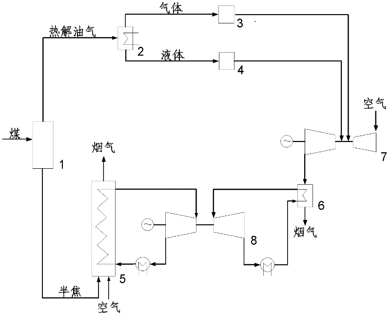
[0052] First, the coal is sent to the pyrolysis device 1; the coal undergoes a pyrolysis reaction in the pyrolysis device 1 to separate out volatile matter, and the pyrolysis gas-liquid product and solid semi-coke are obtained; the pyrolysis gas-liquid product is cooled and separated by the condensation device 2 and separately passed through The gas fuel purification device 3 and liquid fuel purification device 4 for dedusting and desulfurization are purified and sent to the gas turbine 7 to generate electricity; the pyrolyzed solid semi-coke is discharged from the bottom of the pyrolyzer, and the semi-coke enters the steam boiler 5 for combustion to generate steam. At the same time, the gas turbine heat exchange The steam generated by the device 6 is also incorporated into the steam-water system of the steam boiler 5, and the superheated steam enters the steam turbine 8 to generate electricity. Since the steam generated by the heat exchange device 6 after the gas turbine 7 is ...

Embodiment 2

[0055] Raw material: a lignite with high volatile content

[0056] Method of implementation:

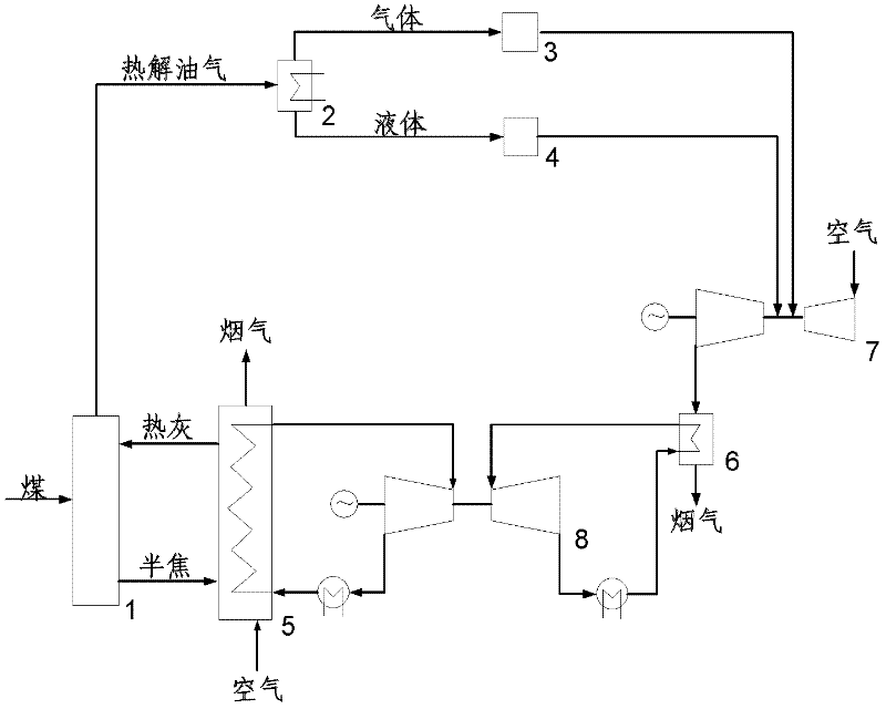
[0057] like image 3 As shown, the coal sample is sent to the pyrolysis device 1 and mixed with part of the hot ash from the circulating fluidized bed boiler 5; the hot ash provides heat to cause the coal to be pyrolyzed in the pyrolysis device 1, and volatile matter is precipitated to obtain gas Liquid products and solid semi-coke; pyrolysis gas-liquid products are cooled and separated by the condensing device 2, and then sent to the gas turbine 7 for power generation after passing through the dust removal and desulfurization purification devices 3 and 4 respectively; the hot flue gas discharged from the gas turbine enters the steam generated by the heat exchange device 6 Power generation by steam turbine 8; pyrolyzed solid semi-coke is discharged from the bottom of the pyrolysis device, semi-coke enters steam boiler 5 and steam generated by combustion enters steam turbine 8 for po...


PUM


Abstract

A hybrid power generation system and method based on classification of solid fuel pyrolysis and semi-coke combustion are provided. The system comprises a pyrolysis device (1) for pyrolysing solid fuel to produce gas, liquid and solid semi-coke fuels, the gas and liquid fuels are separated through a condensing device (2), then separately passed into purification devices (3) and (4) for dedusting and desulfurizing the gas and liquid fuels, and the solid semi-coke fuel is passed into a boiler (5) for combustion to generate steam; a gas turbine (7) for power generation by burning gas and/or liquid fuel, and a steam turbine (8) for steam power generation. The method is carried out by pyrolysing solid fuel to classify solid fuel and produce gas, liquid and solid semi-coke fuels separately entering into gas and steam turbines for power generation, so as to effectively simplify the process, reduce cost, integrate the advantages of the integrated gasification combined cycle (IGCC) and the super-critical power generation technology, and significantly improve the power generation efficiency, it not only can be used in large power plants, but also can be used in small generator sets employing middle or high pressure parameters.

Description

technical field [0001] The invention relates to the technical field of coal power generation, in particular to a staged hybrid power generation system and method based on solid fuel pyrolysis and semi-coke combustion. Background technique [0002] Coal-fired power generation generates high-temperature and high-pressure steam to drive steam turbines to generate electricity. The higher the temperature and pressure of the steam, the higher the efficiency of power generation. Under the conditions of 374.15°C and 22.115MPa, the density of water vapor will increase to be the same as that of liquid water, which is called the critical parameter of water at this time; the parameter higher than this is called supercritical parameter; when the temperature and pressure are higher than 600°C , 25 ~ 28MPa is called ultra-supercritical. [0003] The typical parameters of the subcritical unit are 16.7MPa / 538°C / 538°C, and its power generation efficiency is about 38%; the main steam pressure...

Claims


Application Information

Patent Timeline
IPC IPC(8): F01K23/02C10B53/04C10B53/06C10B53/02C10B57/00
CPCY02E20/14Y02E50/14C10K1/004C10B53/02C10B53/06Y02E20/16F02C3/20Y02E50/12F02C3/28F05D2220/722Y02E20/18Y02E50/11C10K1/02F01K23/067C10B53/04Y02E50/10Y02P20/129Y02P20/54
Inventor 宋文立李俊峰李静海李松庚姚建中林伟刚
Owner INST OF PROCESS ENG CHINESE ACAD OF SCI
Why Eureka
Try Eureka