Driving device of shape memory alloy actuator, driving method thereof, and imaging device using same

A memory alloy, driving device technology, applied in the direction of the mechanism, instrument, installation, etc. that generate mechanical power, can solve the problems of long heat release time and time-consuming

Inactive Publication Date: 2011-11-30
KONICA MINOLTA OPTO
View PDF1 Cites 21 Cited by
  • Summary
  • Abstract
  • Description
  • Claims
  • Application Information

AI Technical Summary

Problems solved by technology

However, in order to return to the above-mentioned martensite phase, it takes a long time for heat release, and it takes time to reach the target position (focus) again

Method used


Image

  • Driving device of shape memory alloy actuator, driving method thereof, and imaging device using same
  • Driving device of shape memory alloy actuator, driving method thereof, and imaging device using same
  • Driving device of shape memory alloy actuator, driving method thereof, and imaging device using same

Examples


Embodiment approach 1

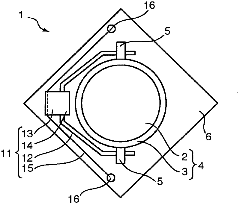
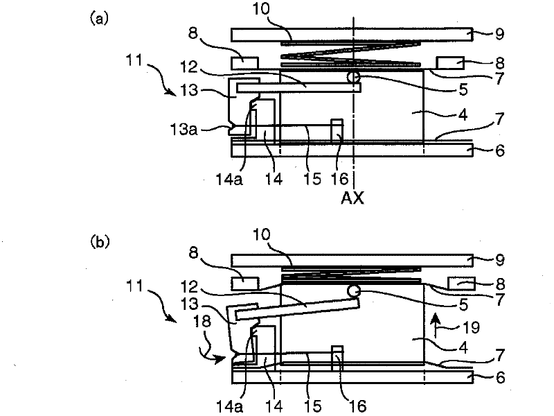
[0025] figure 1 It is a front view (viewed from the lens opening surface) of the autofocus lens drive mechanism 1 of the imaging device in one embodiment of the present invention, figure 2 is a side view for explaining its operation. figure 2 (a) shows that the SMA15 is stretched by the elastic force of the bias spring 10, figure 2 (b) shows the case where the SMA 15 contracts against the elastic force of the bias spring 10 . The drive mechanism 1 performs focusing by displacing the lens 2 in the axis AX (front-rear) direction. The lens barrel 4 includes a lens 2 and a lens driving frame 3 , and the lens 2 is mounted on the lens driving frame 3 . On the outer peripheral surface of the lens barrel 4, a pair of protrusions 5 are formed at the front end (the front end in the above-mentioned front-rear direction), and the protrusions 5 are mounted on the arm portion 12 of the shape memory alloy actuator 11 so that the lens barrel 4 Movement is performed in the direction of...

Embodiment approach 2

[0047] Figure 9 It is a block diagram showing an electrical configuration of a control circuit 31 which is a second driving device for driving the above-mentioned SMA actuator 11 . The control circuit 31 includes a resistance value detection unit 32 , a comparison unit 33 , a microcomputer 34 , an image sensor 25 , a drive control calculation unit 26 , and a drive element 27 , and the drive element 27 controls the drive current flowing into the SMA 15 . This control circuit 31 is similar to the above-mentioned control circuit 21, and the corresponding parts are denoted by the same reference numerals, and description thereof will be omitted. However, in the second embodiment, in the control circuit 31 , the resistance value of the SMA 15 is used as a parameter for detecting the parameter related to the expansion and contraction of the SMA 15 , that is, the position of the lens barrel 4 . Therefore, the resistance value between the electrodes 16 of the SMA15 is detected by the...

Embodiment approach 1

[0056] The driving device of the shape memory alloy actuator in the first embodiment is a driving device of the shape memory alloy actuator that drives the shape memory alloy actuator. It expands and contracts due to heat generation, and the parameter-deformation characteristic related to the expansion and contraction has hysteresis; the movable part is driven by displacement through the above-mentioned expansion and contraction, and the driving device of the above-mentioned shape memory alloy actuator is equipped with: a drive circuit, which controls the above-mentioned shape The memory alloy conducts the above-mentioned energization; the measurement part measures the above-mentioned parameters related to the expansion and contraction of the above-mentioned shape memory alloy; the target displacement position detection part detects the target displacement position of the above-mentioned movable part; and the control part responds from the above-mentioned The output of the meas...


PUM


Abstract

The shape memory alloy actuator drive device (21) is configured such that a shape memory alloy (SMA 15) expands and contracts with temperature changes and has hysteresis for distortion characteristics of parameters regarding that expansion and contraction, wherein the parameter values corresponding to the target positions of a moving part, which is displaced and driven by the expansion and contraction of the SMA (15) as the temperature of the SMA (15) rises and falls, are measured by a measurement part and set as target parameters, the crystal phase of the SMA (15) is pre-martensitic, and the temperature of the SMA (15) is caused to rise or fall so that the parameter value measured by the measurement part passes the target parameter, after which, the temperature of the SMA (15) is again caused to rise or fall so that the parameter measured by the measurement part reaches the target parameter.

Description

technical field [0001] The present invention relates to a driving shape for performing focus adjustment, zoom adjustment, etc. of a lens group constituting an imaging optical system, which is installed in a relatively small imaging device such as a mobile phone with a camera function, and is applied to the imaging device. A drive device for a memory alloy actuator, a drive method thereof, and an imaging device using the drive device. Background technique [0002] In recent years, the number of pixels of an imaging element mounted in a camera-equipped mobile phone or the like has increased dramatically, and image quality has been improved. Accordingly, it is also required to increase the performance of the lens group constituting the imaging optical system. Specifically, it is required to replace the fixed focus method with an automatic focus method, and for the zoom function, it is required to replace the digital zoom with an optical zoom, or to add an optical zoom. Among ...

Claims


Application Information

Patent Timeline
Patent Type & Authority Applications(China)
IPC IPC(8): F03G7/06G02B7/04G02B7/08H02N10/00
CPCG02B7/08F03G7/065H02N10/00G02B7/09F03G7/0614
Inventor 本多泰启三木伸哉
Owner KONICA MINOLTA OPTO
Why Eureka
Try Eureka