Butt mag welding method of low-alloy ultra-high-strength steel and high-quality carbon structural steel after quenching

A carbon structural steel, ultra-high-strength steel technology, applied in welding equipment, welding/welding/cutting items, arc welding equipment, etc. The weld is well formed, the generation of welding defects is reduced, and the effect of reducing welding arcing and arcing points

Active Publication Date: 2011-12-07
HARBIN JIANCHENG GRP
View PDF4 Cites 7 Cited by
  • Summary
  • Abstract
  • Description
  • Claims
  • Application Information

AI Technical Summary

Problems solved by technology

[0003] The purpose of the present invention is to provide a kind of low-alloy ultra-high-strength steel after quenching and high-quality carbon structural steel butt MAG welding method (dissimilar steel MAG welding method), to solve the problem of low-alloy ultra-high

Method used


Image

  • Butt mag welding method of low-alloy ultra-high-strength steel and high-quality carbon structural steel after quenching
  • Butt mag welding method of low-alloy ultra-high-strength steel and high-quality carbon structural steel after quenching

Examples


Example Embodiment

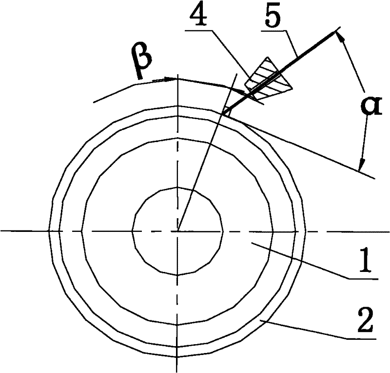
[0016] Specific implementation mode one: as figure 1 and 2 As shown, the welding method described in this embodiment is based on the MAG welding of circular butt joint circular seams of cylindrical parts of dissimilar steel materials, such as 35CrMnSiA low-alloy ultra-high-strength steel and 08Al high-quality carbon structural steel. The specific process of the welding method is as follows:

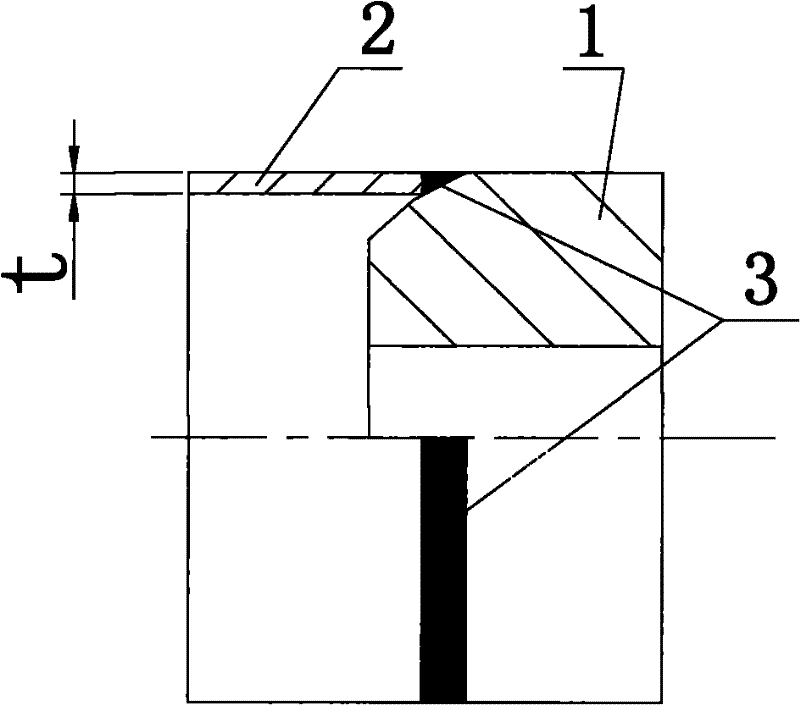
[0017] Step 1, processing the welding port of the 35CrMnSiA cylinder part 1 to be welded and the welding port of the 08Al cylinder part 2 to be welded: the welding end of the thicker 35CrMnSiA cylinder part 1 to be welded is processed into a seam (sealing is also a lock Bottom) bevel form, the lock edge bevel form means that the welding end of the 35CrMnSiA cylinder 1 is tapered in the shape of a truncated cone (the axial cross-sectional profile of the curved surface of the truncated cone is an oblique line or an arc), and the thinner The welding end face of the cylinder part 2 to be wel...

Example Embodiment

[0027] Specific implementation mode two: as figure 1 As shown, in step 1 of this embodiment, the wall thickness t of the 08Al tube 2 is 1.5 mm, and the wall thickness of the 35CrMnSiA tube 1 is 5 to 8 times the wall thickness of the 08Al tube 2 . Other steps are the same as those in Embodiment 1.

Example Embodiment

[0028] Specific embodiment three: In this embodiment, in steps 3 (1) and 3 (2), the preheating temperature before and after tack welding should be lower than the tempering temperature by 50°C; otherwise, the ultra-high strength steel (low alloy ultra-high strength steel is 35CrMnSiA) will have softening problems and affect welding quality. Other steps are the same as those in Embodiment 1 or 2.


PUM


Abstract

The invention relates to a metal active gas (MAG) welding method for butting quenched low-alloy super-high-strength steel and high-quality carbon structural steel and a low-alloy super-high-strength steel MAG welding method, which solve the welding technical problems that the thickness difference and the material performance difference of heterogeneous steel, namely the quenched low-alloy super-high-strength steel and the high-quality carbon structural steel, are large and the weldability of the quenched super-high-strength steel is low. The MAG welding method comprises the following main steps of: machining a part to be welded; quenching and tempering a 35CrMnSiA barrel piece; preheating, tacking and welding; and slowly cooling the 35CrMnSiA barrel piece; and detecting the 35CrMnSiA barrel piece. By the MAG welding method, the weldability of the quenched super-high-strength steel and the carbon structural steel is enhanced; fusion of a welding line is high; and through penetrant flawdetection and coloring flaw detection, the most sensitive crack defects of the super-high-strength steel are not found in a welding bead and a heat affected zone, so the shape of the welding line is good. The MAG welding method belongs to semi-automatic welding; and compared with manual arc welding, the MAG welding method has the advantages of reducing arc striking points and arc receiving points, so that welding defects can be reduced effectively.

Description

technical field [0001] The invention relates to a MAG welding method for low-alloy ultra-high-strength steel, in particular to a MAG welding method for butt ring seams of low-alloy ultra-high-strength steel and high-quality carbon structural steel dissimilar steel after quenching. Background technique [0002] The toughness of low-alloy ultra-high-strength steel (35CrMnSiA) is very poor, especially the butt welding of dissimilar steels after quenching of low-alloy ultra-high-strength steel (35CrMnSiA) is very difficult. At present, there is no provision in the prior art for low-alloy ultra-high-strength steel (35CrMnSiA) after quenching (performance is σ b ≥1620MPa, HRC45~55, Ak≥36J) and high-quality carbon structural steel (08Al) MAG welding method of dissimilar steel. Contents of the invention [0003] The purpose of the present invention is to provide a kind of low-alloy ultra-high-strength steel after quenching and high-quality carbon structural steel butt MAG welding...

Claims


Application Information

Patent Timeline
IPC IPC(8): B23K9/173B23K9/235B23K103/18
Inventor 刘立成许连辅邹玉宏陈广强武永和
Owner HARBIN JIANCHENG GRP
Why Eureka
Try Eureka