
A design method for multi-level multi-surface complex solar energy concentrating heat collection system

A system design, solar heat flow technology, applied in the direction of information technology support system, computing, special data processing applications, etc., can solve the problems that cannot meet the calculation requirements, cannot comprehensively consider the system type, optical efficiency, light and heat distribution uniformity, and cannot analyze data And other issues

Inactive Publication Date: 2011-12-07
XI AN JIAOTONG UNIV
View PDF1 Cites 14 Cited by
  • Summary
  • Abstract
  • Description
  • Claims
  • Application Information

AI Technical Summary

Problems solved by technology

However, general solar concentrating heat collection systems (such as tower, trough or dish, etc.) are complex systems with multiple levels and multiple surfaces.
In this regard, the existing commercial optical software in the optical field has limitations in calculation accuracy and specific statistics, and cannot meet the specific calculation requirements in this field, especially for multi-order multi-surface complex irregular absorption surfaces or absorbers. The problem of solving the light propagation process and heat flux distribution, and the inability to perform further data analysis and coupling to fluid heat transfer calculations
Therefore, it is impossible to comprehensively consider various design requirements such as system type, optical efficiency, uniformity of light and heat distribution, working fluid flow performance, system thermal performance (or thermal efficiency) and operating conditions to carry out multi-level multi-surface complex Efficient Design of Solar Concentrating Heat Collection System

Method used


Image

  • A design method for multi-level multi-surface complex solar energy concentrating heat collection system
  • A design method for multi-level multi-surface complex solar energy concentrating heat collection system
  • A design method for multi-level multi-surface complex solar energy concentrating heat collection system

Examples


Embodiment Construction

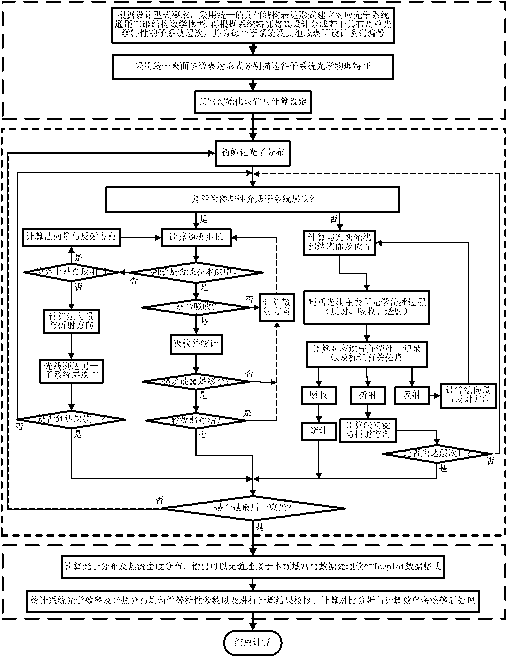
[0024] The present invention will be described in further detail below in conjunction with the accompanying drawings.

[0025] Design Phase I:

[0026] (1) According to the design type requirements of the multi-level multi-surface complex solar energy concentrating heat collection system to be designed, such as various types of systems such as tower type, trough type or dish type, establish a general three-dimensional mathematical model corresponding to the optical system, including general three-dimensional Establishment of geometric structure model and its simplified division and description of optical physical characteristics.

[0027] 1a) See attached figure 1 According to the requirements of the design type, a unified geometric structure expression form is designed and adopted to establish a general three-dimensional geometric structure model of the optical system corresponding to the design type (such as tower type, trough type, or dish type, etc.). That is, the three-...


PUM


Abstract

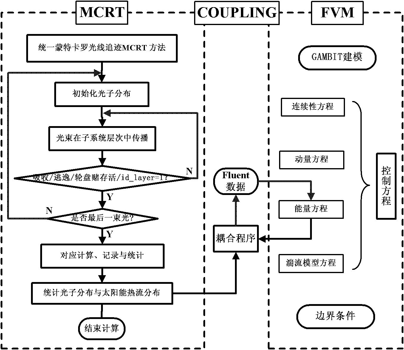
The invention discloses a design method of a multi-level and multi-surface complex solar concentrating heat collection system, comprising the following steps of: firstly, according to requirements on design types, establishing a universal three-dimensional mathematical model corresponding to an optical system; subsequently, performing optical calculation by a uniform Monte Carlo ray tracing method; and then, taking optical efficiency and uniformity of distribution of light and heat as examination basis, until the designed system meets the design requirements on the needed optical efficiency and uniformity of distribution of light and heat; establishing a corresponding numerical calculation module in a universal computational fluid and a heat transfer platform under a required operation condition; coupling a solar heat flux distribution calculated by the Monte Carlo ray tracing method with the numerical calculation model so as to perform light-heat-fluid coupling calculation; and then,further taking the flowing heat transfer performance of a working medium fluid in the system and the system thermal performance as the examination basis, until the designed system completely meets various design requirements on the optical efficiency, the uniformity of distribution of light and heat, the flowing performance of the working medium, the system thermal performance and the like.

Description

technical field [0001] The invention belongs to the technical field of solar heat utilization, and in particular relates to a design method for a multi-stage multi-surface complex solar energy focusing heat collection system capable of effectively calculating the light propagation process, heat collection characteristics, solar heat flow distribution characteristics and working medium flow heat transfer characteristics in the system . Background technique [0002] With economic development, industrial energy consumption continues to increase, and the energy crisis is becoming more and more serious. The research on the development of new energy and its low-cost and high-efficiency utilization is very important. The development of solar thermal power generation technology has become an important research task we are facing at this stage. [0003] During the "Eleventh Five-Year Plan" period, the country continued to promote the rapid development of solar thermal utilization, an...

Claims


Application Information

Patent Timeline
IPC IPC(8): G06F17/50
CPCY02E60/76Y04S40/22Y02E60/00
Inventor 何雅玲程泽东崔福庆陶于兵
Owner XI AN JIAOTONG UNIV
Learn More