Automobile Braking System with Micro-clutch Type Accelerator Error Correction Device

An error correction device and automobile brake technology, which is applied in the field of automobile brakes, can solve problems such as wrong gas pedal signal error, difficulty in finding a suitable location for installation, poor system reliability, etc., and achieve accurate displacement length, accurate position, and good reliability. Effect

Inactive Publication Date: 2011-12-14
颜昌松
View PDF2 Cites 5 Cited by
  • Summary
  • Abstract
  • Description
  • Claims
  • Application Information

AI Technical Summary

Problems solved by technology

The first disadvantage of this technology is that the continuously changing pressure signal sensed by the annunciator is taken out of the misstepped accelerator signal. When the signal acquisition device fails, it may cause errors in the judgment of the misstepped accelerator signal, resulting in poor reliability of the system.
The second disadvantage of this technology is to use the signal output line to control the electric valve, and use the electric valve to control the vehicle's engine oil supply pipe, ignition circuit, motor power supply and other power sources of the vehicle, so that the driver will accidentally step on the accelerator until the vehicle is stopped. Long, the vehicle has a long trip to make an error, and this slow response is not good for preventing traffic accidents.
[0003] In his patent application 201110030092.4 "A

Method used


Image

  • Automobile Braking System with Micro-clutch Type Accelerator Error Correction Device
  • Automobile Braking System with Micro-clutch Type Accelerator Error Correction Device
  • Automobile Braking System with Micro-clutch Type Accelerator Error Correction Device

Examples


Embodiment 1

[0034] Embodiment 1. Automobile braking system with micro-clutch type misstepping accelerator error correction device

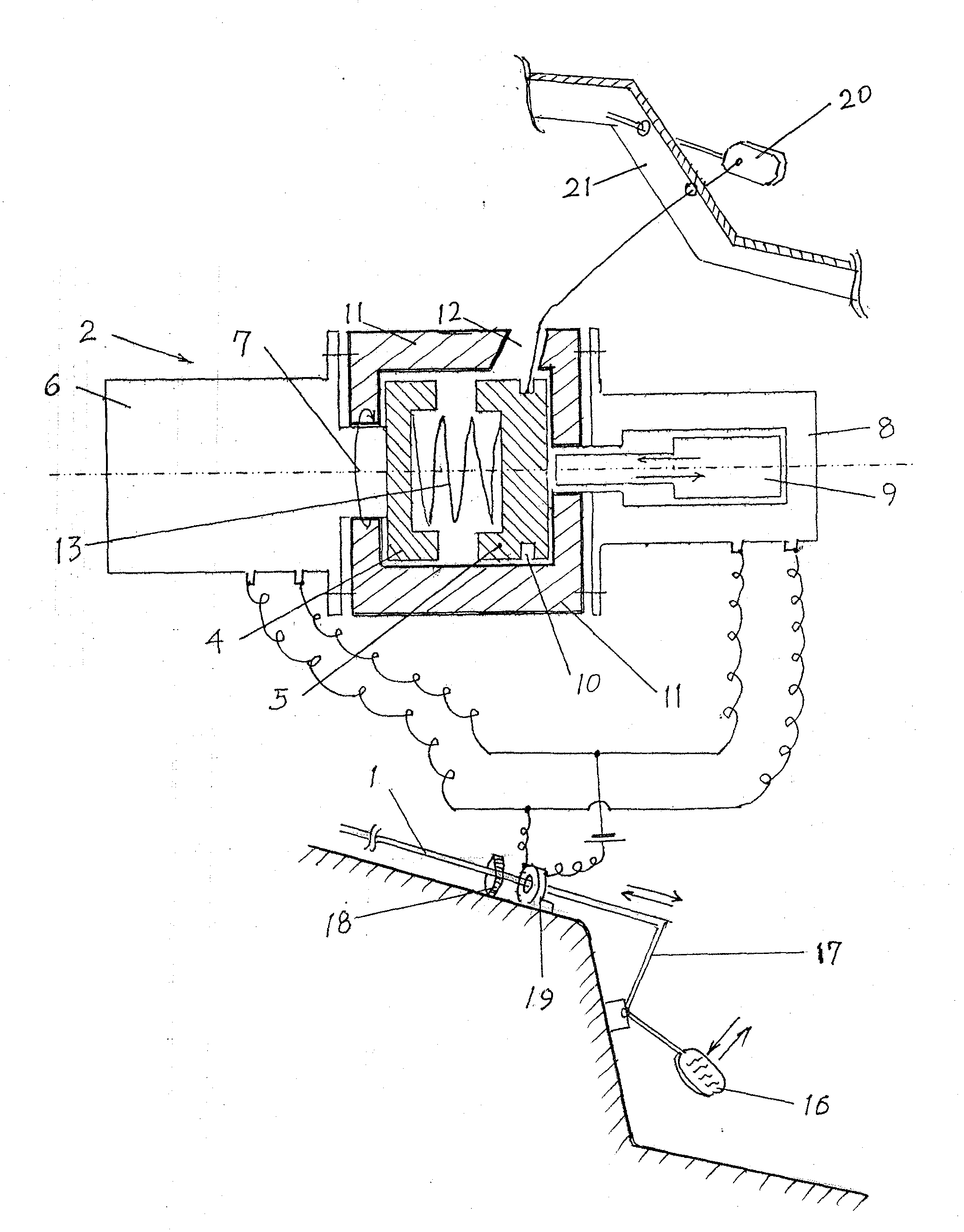
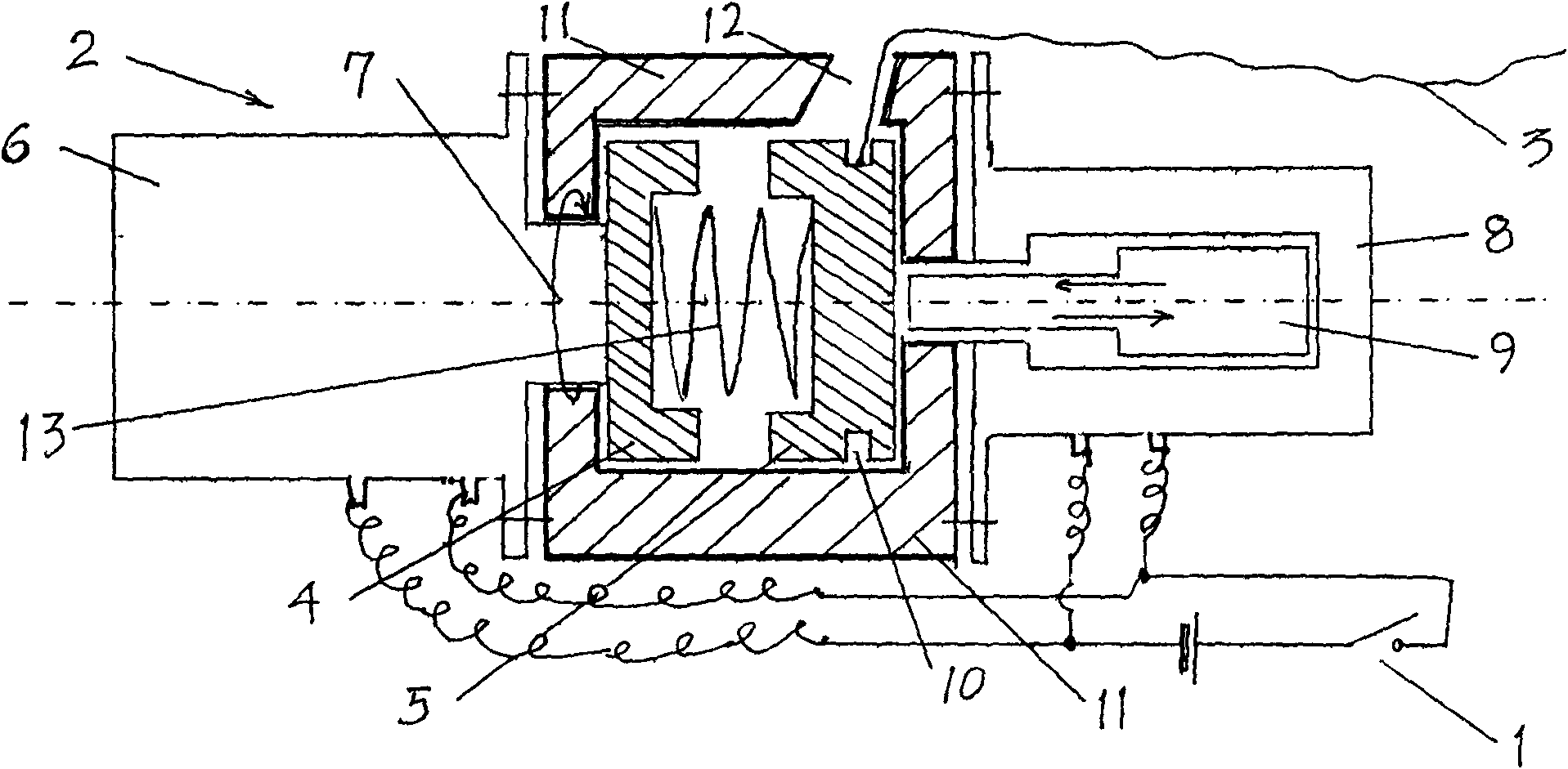
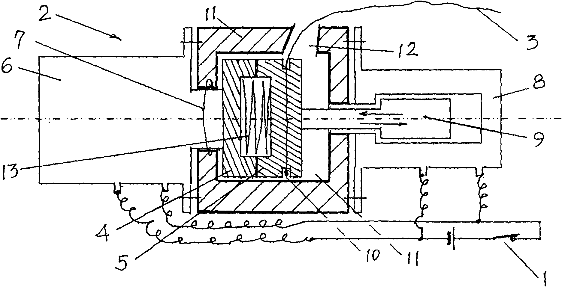
[0035] Such as figure 1 , 2 , 3, 4, 7. This automobile braking system comprises the accelerator connecting rod 17 that is connected with the accelerator pedal 16, the brake pedal 20 of the automobile and the micro-clutch type misstepping accelerator error correction device; The parts of stepping on the gas pedal by mistake, the brake pull cord 3 of the error correction device is the part that can pull the brake pedal 20 to realize the brake.

[0036] The error correction device includes a pressure type low voltage electric switch 1, a jaw type micro clutch 2 and a brake pull rope 3. in:

[0037] The pressure type low-voltage electric switch 1 is selected for use in being subjected to 5-50 kilogram pressure zone, when a certain pressure value, the electric switch that can conduct.

[0038] The low-voltage motor 6 in the jaw type micro clutch 2 selects DC ...

Embodiment 2

[0046] Embodiment 2. Automobile braking system capable of flexible braking with a micro-clutch type misstepping accelerator error correction device

[0047] As in the whole structure of embodiment 1, and the bottom 14 of the recessed ring 10 is a cam 15 shape, as Figure 5 , 6 . The relative position structure of the cam 15, the jaw disc shell 11 guide wire hole 12, and the brake pull cord 3 is: when the active jaw disc 4 and the driven jaw disc 5 are in the separated state, that is, the pressure-type low-voltage motor When the switch 1 is closed and non-conductive, the long axis of the cam 15 is located on the side close to the guide rope hole 12 of the inlay disc shell 11; The connecting line of 11 guide rope holes 12 is cam 15 tangents. That is to say, when the error correction device was in a non-working state, the rope guide hole 12 and the brake pull cord 3 were all on the side of the long axis of the cam 15 . When the error correction device started working, the bra...

Embodiment 3

[0049] Embodiment 3. An automobile brake system with a micro-clutch type misstepping accelerator error correction device using an electronic throttle as a pressure-type low-voltage electric switch

[0050] As the whole structure of embodiment 2, but the pressure-type low-voltage electric switch 1 is to borrow the electronic gas pedal of automobile, there is the function that just can output the switch electrical signal above a certain set pressure in the electronic throttle software of this automobile.


PUM

PropertyMeasurementUnit
Perimeteraaaaaaaaaa

Abstract

A pressure trigger switch-type accelerator pedal system used to correct mistaken use of an accelerator for braking, classed as an accelerator system able directly to obtain a signal indicating that the accelerator has been pressed incorrectly. A pressure trigger switch (1) is provided on the front surface or rear surface of the accelerator pedal (16), or alternatively, a pressure trigger switch (1) is provided at the part of the car bodywork (21) corresponding to the accelerator pedal (16); when a spring element in the pressure trigger switch is deformed by pressure at the switching threshold, two conducting contact elements of the switch are brought into contact, generating a switch that is switched on so that it conducts electricity; the position in which the pressure trigger switch (1) is disposed enables the switching threshold to correspond to the threshold for incorrect accelerator-pedal use; the pressure trigger switch (1) is connected to a trigger signal converter (35). The present accelerator pedal system is able directly to obtain a signal indicating that the accelerator has been pressed incorrectly, and there is no need to use a pressure sensor with a microelectronic circuit to analyse actions of accelerator-pressing at different pressures to determine whether the accelerator has been pressed incorrectly; the system has a fast response speed, simple structure, low cost and small volume; the system is easy to install, and is a reliable system for obtaining a signal indicating incorrect pressing of an accelerator.

Description

technical field [0001] The invention belongs to the technical field of brakes for automobiles, in particular to a brake system for automobiles capable of transforming the mechanical action of stepping on the gas pedal by mistake into an automatic braking mechanical action. Background technique [0002] In his authorized patent 200510022077.X "throttle system device with annunciator", the applicant provides a device that has the ability to judge whether the throttle action is correct or wrong before determining whether to remedy and brake, so that the throttle can be controlled. A motor vehicle accelerator pedal system capable of moving and accelerating. It is characterized in that an annunciator is arranged on any one of the accelerator pedal, the linkage device and the vehicle body device. The annunciator is connected with the electric valve that can cut off the engine oil circuit and the electric valve on the wheel brake. This technology proposes to use electronic settin...

Claims


Application Information

Patent Timeline
IPC IPC(8): B60T7/06B60K26/02
CPCB60K26/02B60T7/042F02D11/02B60W50/087B60W50/10B60T17/18B60T17/221
Inventor 颜昌松
Owner 颜昌松
Why Eureka
Try Eureka