
Air leakage control system and control method for air pre-heater

An air preheater and control system technology, applied in combustion methods, lighting and heating equipment, indirect carbon dioxide emission reduction, etc., can solve the problems of economic loss, non-adjustment, loss of function, etc. strong effect

Active Publication Date: 2013-09-11
SHANGHAI ORIENTAL MARITIME ENG TECH CO LTD
View PDF4 Cites 2 Cited by
  • Summary
  • Abstract
  • Description
  • Claims
  • Application Information

AI Technical Summary

Problems solved by technology

It can be seen from this that whether the air leakage control system can work depends entirely on whether the sensor can work normally. If the sensor fails, the air preheater needs to be shut down for repair, which will affect the overall operating efficiency of the generator set and cause certain damage. Economic losses
[0005] In addition, at present, the gap sensors in the air leakage control system mainly use contact sensors and non-contact sensors that are fixedly installed. The contact sensors will wear out after a long time of operation, and must be replaced in a maintenance cycle, which is inconvenient to replace and maintain; The non-contact type mostly uses eddy current sensors. The eddy current sensor is fixedly installed on the sector plate. Since it cannot be adjusted, the installation of the eddy current sensor has a great influence on the levelness of the sector plate, the levelness and height of the radial sealing plate, and the rotor. There are requirements for the maximum amount of deformation. When the above indicators do not meet the requirements, the eddy current sensor will lose its function, resulting in the failure of the entire air leakage control system. Therefore, most of the current air leakage control systems using eddy current sensors cannot be used normally.

Method used


Image

  • Air leakage control system and control method for air pre-heater
  • Air leakage control system and control method for air pre-heater
  • Air leakage control system and control method for air pre-heater

Examples


Embodiment Construction

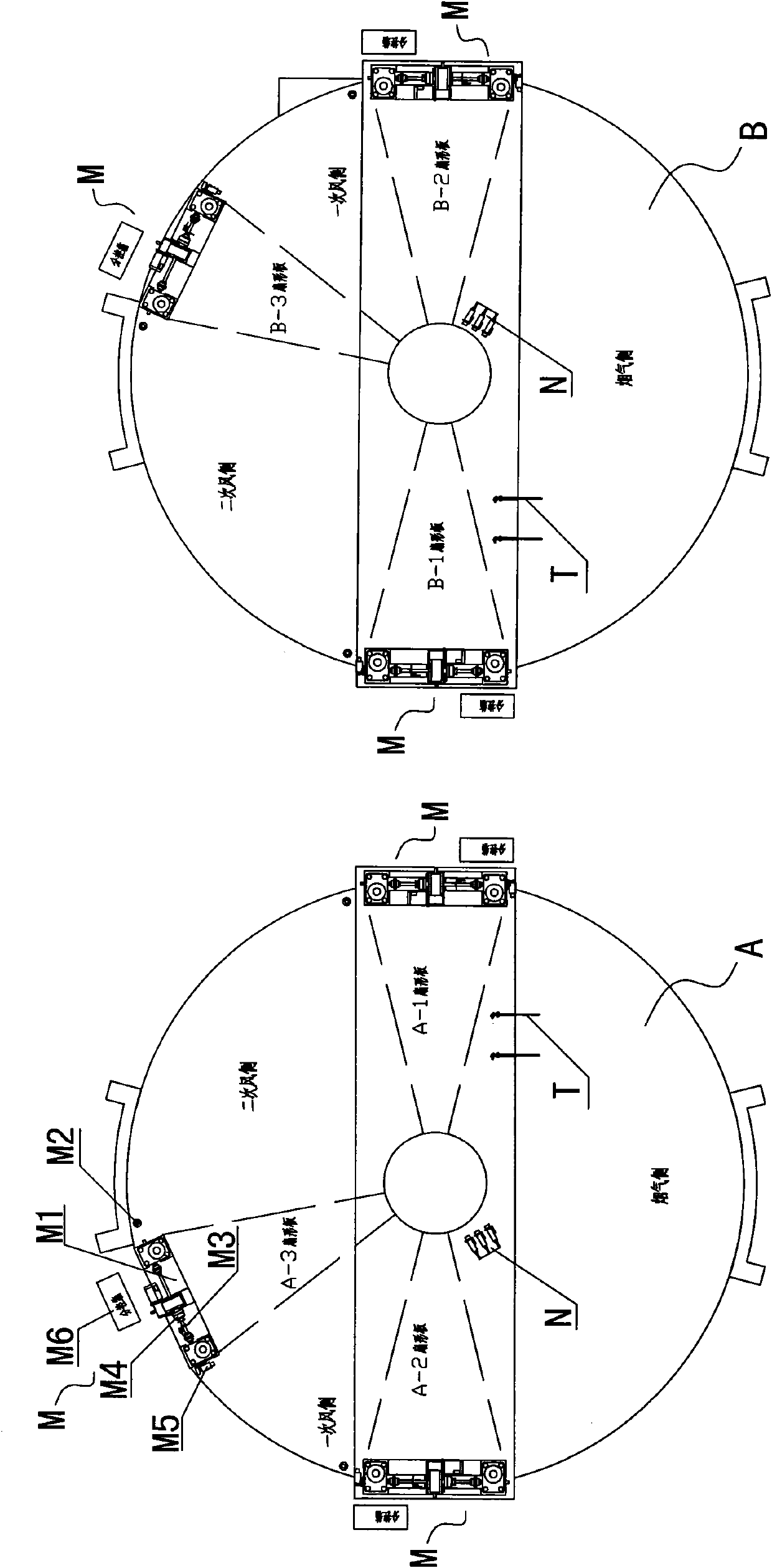
[0044] The air leakage control system includes a control unit, a fan-shaped plate execution unit M corresponding to the fan-shaped plate one-to-one, and a temperature detection device T corresponding to the air preheater one-to-one. The rotor speed measuring device N. Such as figure 1 As shown, in this embodiment, the generator set (boiler) is equipped with two air preheaters with three compartments, namely the first air preheater A and the second air preheater B, wherein the first air preheater Heater A is equipped with three fan-shaped plates, which are respectively fan-shaped plates A-1, A-2 and A-3, and the second air preheater B is equipped with three fan-shaped plates, which are respectively fan-shaped plates B-1, B-2 and B-3. ​​Therefore, in this embodiment, the air leakage control system includes a control unit and six sets of fan-shaped plate execution units, and preferably also includes a rotor speed measuring device N installed on the first air preheater A and a te...


PUM


Abstract

The invention discloses an air leakage control system and an air leakage control method for an air pre-heater. The system comprises a main control unit, a fan-shaped plate execution unit and a temperature detection device; a sensor device of the fan-shaped plate execution unit transmits the acquired current signals for reflecting gaps of respectively corresponding fan-shaped plates and radial sealing sheets to the control unit; the temperature detection device transmits the acquired temperature signals to the control unit; and the control unit selectively controls a lifting mechanism of the execution unit according to the current signals or the temperature signals to drive the fan-shaped plates to move up and down. According to the air leakage control system, when the sensor device fails,the control unit can regulate the positions of the fan-shaped plates through the temperature signals acquired by the temperature detection device, and an operator can overhaul and regulate the sensordevice in the temperature control process or the air pre-heater does not need to work, so the system is very important in the field, for abnormal halt produces huge loss.

Description

technical field [0001] The invention relates to the problem of air leakage control of an air preheater, in particular to an air leakage control system and a control method of an air preheater. Background technique [0002] The air preheater is a heat exchange device that uses the heat of flue gas to heat the air required for combustion. The air preheater can not only absorb the heat in the exhaust gas, reduce the temperature of the exhaust gas, thereby improving the efficiency of the boiler, but also because the air is preheated, it can strengthen the ignition and combustion process of the fuel, reduce the heat loss of the incomplete combustion of the fuel, and further improve the efficiency of the boiler. Increased boiler efficiency. In addition, air preheating can also increase the temperature of flue gas in the furnace and enhance the radiation heat transfer in the furnace. [0003] The main problem of the air preheater is air leakage, so the air preheater is provided w...

Claims


Application Information

Patent Timeline
Patent Type & Authority Patents(China)
IPC IPC(8): F23L15/00
CPCY02E20/34
Inventor 秦海瑞王立刚马玉顺匡俊顾兆毅杨迪
Owner SHANGHAI ORIENTAL MARITIME ENG TECH CO LTD
Learn More