High-strength reinforcement built-in ultra high performance concrete (UHPC) beam member

A technology of ultra-high-performance and high-strength steel bars, which is applied in the direction of building components, building reinforcements, joists, etc., can solve the problems of difficult construction, insufficient compressive strength, and high construction costs, so as to reduce the consumption of raw materials and energy, The effect of increasing the available space and reducing the difficulty of construction

Inactive Publication Date: 2011-12-21
BEIJING UNIV OF TECH
View PDF3 Cites 25 Cited by
  • Summary
  • Abstract
  • Description
  • Claims
  • Application Information

AI Technical Summary

Problems solved by technology

[0004] Ordinary reinforced concrete beams have the following defects when facing high-rise, heavy-load, and long-span structures: due to the low strength of concrete and steel bars, in high-rise, long-span structures, the load is relatively large, and only by increasing the beam section size and The method of reinforcing the reinforcement increases its bearing capacity, which not only causes a great loss of materials, increases the construction cost and construction difficulty, but also severely compresses the available space due to the large cross-section; It has been cracked, and the crack appears in the form of a wide main crack. If the crack is too large, the stiffness of the beam will be reduced, the deflection will be too large, and the durability will be reduced. The service life is greatly reduced
[0005] Although prestressed reinforced concrete beams can partly avoid the above defects, because the compressive strength of ordinary concrete and high-performance concrete is still not high enough, the cross-section is still too large when facing high-rise and long-span structures, and the application of prestress increases the construction difficulty and construction cost; although the above-mentioned defects can be avoided by using ultra-high performance concrete beams with prestressed steel bars, there are still problems of high construction difficulty and high construction cost

Method used


Image

  • High-strength reinforcement built-in ultra high performance concrete (UHPC) beam member
  • High-strength reinforcement built-in ultra high performance concrete (UHPC) beam member
  • High-strength reinforcement built-in ultra high performance concrete (UHPC) beam member

Examples


Embodiment 1

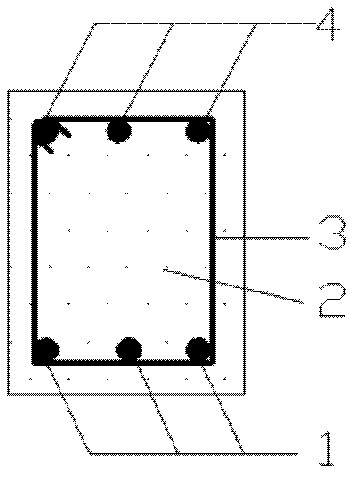
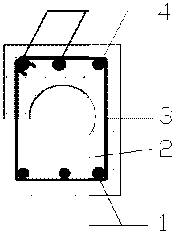
[0028] This embodiment corresponds to figure 1 The solid rectangle shown and figure 2 For the hollow rectangular section shown, first make the outer formwork according to the size of the section. figure 2 The hollow section shown still needs to make an inner formwork, the outer formwork adopts steel formwork or wood formwork, and the inner formwork adopts the same material as the outer formwork. When the inner formwork is circular, an inflatable rubber bag can also be used.

[0029] Secondly, the reinforcing bar skeleton is bound, and the reinforcing bar skeleton is made up of tensile reinforcing bar 1, stirrup 3 and longitudinal compression reinforcing bar 4, and longitudinal tensile reinforcing bar 1 and longitudinal compression reinforcing bar 4 are attached to the inner side of stirrup 3 and bound together with it; Longitudinal tension reinforcement 1 adopts high-strength reinforcement, stirrup 3 and longitudinal compression reinforcement 4 can adopt high-strength reinf...

Embodiment 2

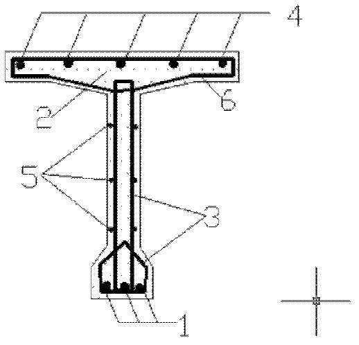
[0032] This embodiment corresponds to image 3 For the T-shaped section shown, first make the outer formwork according to the size of the section, and the outer formwork is made of steel formwork.

[0033] Secondly, the reinforcement skeleton is bound. The reinforcement skeleton is composed of tension reinforcement 1, stirrup 3, longitudinal compression reinforcement 4, distribution reinforcement 5 and roof stress reinforcement 6. The longitudinal tension reinforcement 1 is attached to the inner side of the stirrup 3 and connected with it. Binding together, the distribution reinforcement 5 is attached to the outer side of the stirrup 3 and bound together; the longitudinal compression reinforcement 4 is attached to the inner side of the roof stress reinforcement 6, and the roof stress reinforcement 6 is connected to the stirrup 3 to form an effective connection; Among them, the longitudinal tensile reinforcement 1 and the roof stress reinforcement 6 are high-strength reinforcem...

Embodiment 3

[0036] This embodiment corresponds to Figure 4 For the box section shown, the formwork is first made according to the size of the section, and the inner and outer formworks are all made of steel formwork.

[0037] Secondly, the reinforcement skeleton is bound, and the reinforcement skeleton is composed of tensile reinforcement 1, stirrup 3, longitudinal compression reinforcement 4, distribution reinforcement 5 and roof stress reinforcement 6. Among them, the stirrup 3 forms a closed double layer, the longitudinal tensile steel bar 1 is attached to the inner side of the stirrup 3 and bound together with it, and the distribution steel bar 5 is arranged on the inner and outer sides of the box girder web at the same time and attached to the inner side of the stirrup 3 The outer side is bound together with it; the longitudinal compression steel bar 4 is attached to the inner side of the top plate stress steel bar 6, and the roof stress steel bar 6 is connected with the stirrup 3 t...


PUM


Abstract

The invention provides a high-strength reinforcement built-in ultra high performance concrete (UHPC) beam member, which is particularly suitable for the field of beam members with high-rise, heavy load and long span structures. The member comprises UHPC and a reinforcement cage which is poured inside and is formed by high-strength reinforcement and common reinforcement. The beam member has the following advantages: the advantages of the UHPC and the high-strength reinforcement are fully utilized, thus effectively reducing the section of the member, improving the ductility of the member and enlarging the available space while saving materials and energy; and the beam member dispenses with application of prestress, has simple construction process, is suitable for prefabrication production, improves the construction speed and is beneficial to popularization and application of the two materials in the engineering and research and development of novel materials.

Description

technical field [0001] The invention is an ultra-high-performance concrete beam member with built-in high-strength steel bars, and is especially suitable for the field of high-rise, heavy-load, and long-span reinforced concrete beam members. Background technique [0002] Ultra High Performance Concrete (UHPC for short), also known as Reactive Powder Concrete (RPC for short), is based on the theory of maximum compactness, removes coarse aggregate, and improves the fineness and Active, and mixed with steel fibers, strict preparation and construction techniques are adopted to minimize the defects (pores and micro-cracks) inside the material, with ultra-high strength, high toughness, high durability, high crack resistance and volume A new cement-based composite material with good stability. The compressive strength of ultra-high performance concrete is 3-15 times that of high-strength concrete, the tensile strength is 4-6 times that of high-strength concrete, the ultimate tensi...

Claims


Application Information

Patent Timeline
Patent Type & Authority Applications(China)
IPC IPC(8): E04C3/20E04C5/01
Inventor 邓宗才徐海宾
Owner BEIJING UNIV OF TECH
Why Eureka
Try Eureka