
Quantitative analysis device and analysis method for multi-component cooking fume concentration

A technology for oil fume concentration and quantitative analysis, which is used in measurement devices, analysis materials, and material analysis by optical means.

Inactive Publication Date: 2011-12-21
SOUTH CHINA UNIV OF TECH
View PDF3 Cites 13 Cited by
  • Summary
  • Abstract
  • Description
  • Claims
  • Application Information

AI Technical Summary

Problems solved by technology

[0003] Oil fume detection is a complex task, and there are many equipment and methods for oil fume detection in the domestic and foreign markets, such as (1) traditional infrared spectrophotometry, through sampling, extraction, measurement, and calculation of oil fume, the oil fume Concentration, which can accurately detect and calculate the concentration of oil fume, but the required sampling time and the time period for obtaining data are long
(2) The gas detection tube method uses a catalyst to decompose the oil fume and concentrated sulfuric acid, and judges the oil fume concentration by visually observing the depth of the dark reactant. This method is fast, simple, and low in cost, but it cannot monitor the oil fume concentration in real time; (3) The oil fume remote wireless monitoring system based on the gas sensor can detect the oil fume concentration in real time, but the detector is easily covered by the oil fume, resulting in a short service life, and the oil fume filtered by the metal filter is quite different from the standard oil fume
To sum up, the existing detection technologies all have problems such as poor real-time performance, short life, and low precision.

Method used


Image

  • Quantitative analysis device and analysis method for multi-component cooking fume concentration
  • Quantitative analysis device and analysis method for multi-component cooking fume concentration
  • Quantitative analysis device and analysis method for multi-component cooking fume concentration

Examples


Embodiment Construction

[0022] The implementation of the present invention will be further described below in conjunction with the accompanying drawings, but the implementation and protection scope of the present invention are not limited thereto.

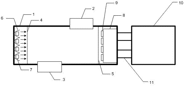
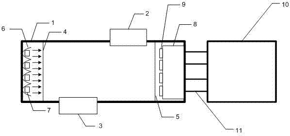
[0023] as attached figure 1 As shown, a multi-component oil fume concentration quantitative analysis and detection device includes a trachea housing 1, an oil fume inlet 2, an oil fume outlet 3, a first quartz glass sheet 4, a second quartz glass sheet 5, a concave condenser mirror 6, Infrared light source 7, pyroelectric detector 8, optical filter 9, signal processing circuit 10 and pyroelectric detector output pin 11.

[0024] Four infrared light sources 7 are installed side by side at one end of the trachea shell 1, and the pyroelectric detector 8 is installed at the other end of the trachea shell 1, and the four detection channels of the pyroelectric detector 8 are respectively equipped with filters of different wavelengths 9. Each infrared light sou...


PUM

PropertyMeasurementUnit
wavelengthaaaaaaaaaa

Abstract

The invention relates to a multi-component oil fume concentration quantitative analysis device and its analysis method. The analysis device includes a signal processing circuit, a trachea shell, an oil fume inlet, an oil fume outlet, a first quartz glass sheet, a second quartz glass sheet, Pyroelectric detectors and four infrared light sources; the four infrared light sources are installed side by side at one end of the trachea housing, the pyroelectric detectors are installed at the other end of the trachea housing, and the four pyroelectric detectors The detection channels are respectively equipped with filters of different wavelengths, and each infrared light source is respectively facing a detection channel of the pyroelectric detector; the output end of the pyroelectric detector is connected with a signal processing circuit. The analysis method obtains the ratio F of the gas detection channel and the reference channel through the device, and according to the characteristics of the pyroelectric detector and Lambert-Beer's law, respectively substitutes into the fitting formula to obtain the substance concentration at the corresponding wave number. The invention has the advantages of real-time, quantitative and high sensitivity.

Description

technical field [0001] The invention relates to an analysis device and method for oil fume concentration, in particular to a multi-component oil fume concentration quantitative analysis device and an analysis method thereof. Background technique [0002] With the rapid development of social economy, the tertiary industry is also booming. Because the planning, construction and management of the catering industry are seriously lagging behind, the cooking fume pollution it produces seriously affects the normal life of the surrounding residents. Therefore, the problem of cooking fume pollution in the catering industry disturbing residents has become one of the environmental problems that have received the most complaints from environmental petitioners in recent years. The air pollutants emitted by cooking fumes are mainly aerosols, which contain volatiles of edible oil and food at high temperature, as well as aldehydes, ketones, alkanes and chains formed by oxidation, cracking ...

Claims


Application Information

Patent Timeline
Patent Type & Authority Applications(China)
IPC IPC(8): G01N21/35G01N21/3504
Inventor 秦华标吕善翔李雪梅王兆山
Owner SOUTH CHINA UNIV OF TECH
Learn More