
Optical multi-point touch screen device and method applicable to vibration and damp environment

A multi-touch screen, wet environment technology, applied in the input/output process of data processing, instruments, electrical and digital data processing, etc. Destruction and other problems to achieve the effect of removing ghost points

Inactive Publication Date: 2014-05-14
NO 709 RES INST OF CHINA SHIPBUILDING IND CORP
View PDF8 Cites 0 Cited by
  • Summary
  • Abstract
  • Description
  • Claims
  • Application Information

AI Technical Summary

Problems solved by technology

Traditional interactive devices such as trackballs and keyboards can no longer meet the control requirements of the three-dimensional electronic sand table platform on large-screen display devices, and the requirements for large-screen multi-touch interactive devices with intuitive and convenient operation are put forward
[0003] Most of the multi-touch screen technologies appeared after 2005, and most of the patented technologies, including capacitive and resistive multi-touch technologies, cannot meet the multi-touch requirements of large-screen displays.
For example, the "multi-touch screen" applied by Apple, the application number is 200580011740.4, the patent uses a multi-layer capacitive sensing medium as a touch panel, due to the problem of medium ductility, only small-sized capacitive multi-touch screens below 20 inches can be manufactured; In addition, this patent uses the current flowing from the touch fingertip to the capacitive sensing medium as the sensing method, which cannot be applied to the requirements of wet and harsh environments such as shipboard.
Another example is the "resistive touch screen body, touch screen controller and multi-touch point recognition method" applied by BYD Company. The application number is 200810210113.9. The problem is that only small and medium-sized capacitive multi-touch screens of 24 inches and below can be manufactured; in addition, because the conductive coating will gradually wear out with the increase in the number of uses and eventually fail, it cannot meet the durability requirements of the military environment
[0004] Although some other patented technologies can meet the multi-touch requirements of large-screen displays, their structural characteristics determine that they cannot be applied to small spaces or harsh environments that are prone to moisture, condensation, and long-term vibration, such as military environments such as ships.
One type can only be applied to projection-type large-screen display equipment, such as "Multi-point and object touch screen device and multi-touch positioning method" applied by Chen Weishan, the application number is 200810065714.5, this patent can only be applied to projection-type large-screen display equipment , cannot be used in liquid crystal and plasma flat-panel display devices, and is not suitable for military environments with narrow spaces such as shipboard
The other type is mainly infrared multi-touch screen technology, which cannot adapt to the harsh environment of long-term vibration. For example, "A Recognition Method for Infrared Touch Screen Multi-touch" applied by Jintian Touch, the application number is 201010224550.3. This patent uses infrared emission tubes One-to-one correspondence with the receiving tube is used as a sensing means, and the directivity requirements of the infrared emitting tube and the receiving tube are strict. After long-term vibration, the directivity is damaged, which will cause the touch screen to fail. It is not suitable for the harsh environment of long-term vibration. Such as vehicle and ship environment
[0005] There is also a newer optical multi-touch technology, such as the "OPTICAL TOUCH SCREEN ASSEMBLY" applied by Klony Lieberman et al., the application number is US2009 / 0200453A1, and the "solution to the multi-touch scenario of the optical touch screen" applied by NextWindow company. System and method", the application number is PCT / US2009 / 033624 / 200980108845.X, in a humid environment, the surface of the lens of its imaging structure will condense into a layer of small water droplets, which cannot be imaged and cause the touch screen to fail to work normally, so it is not applicable In the harsh environment of humidity and easy condensation; another example is "a multi-point touch screen" applied by DANG Ren, the application number is 200810024770.4. In addition to the problem of condensation on the lens surface, there are two problems: one is as described in the 2 pages of its manual and As mentioned on page 5, when the touch system is working, the image formed by the reference object is a continuous line segment, and the angle of view perpendicular to the direction of the touch screen is small, which requires high sensor installation accuracy. Simply increasing the pixel length is not suitable for long-term vibration And the improvement of the tolerance of touch screen deformation is very limited; the second is the method of directly calculating the angle with the number of sensor pixels obtained by statistics to perform triangulation as described on page 3 of its manual. Due to the optical imaging distortion of the lens, there is a high center accuracy. , the problem of low precision around, directly use this triangulation positioning method in a place far from the center of the screen due to large position errors, and it is difficult to distinguish between two touch points that are close

Method used

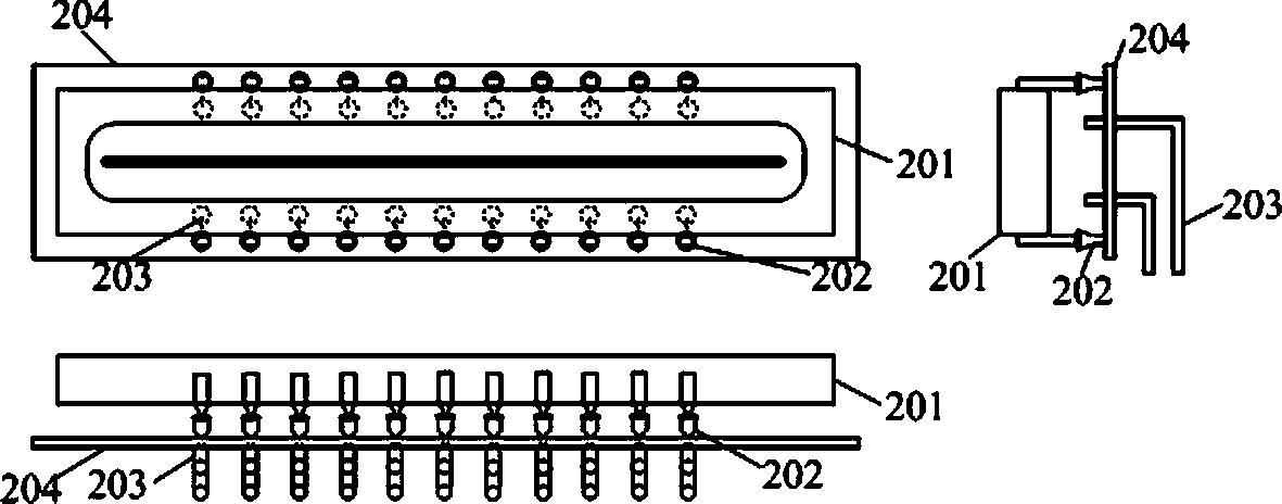
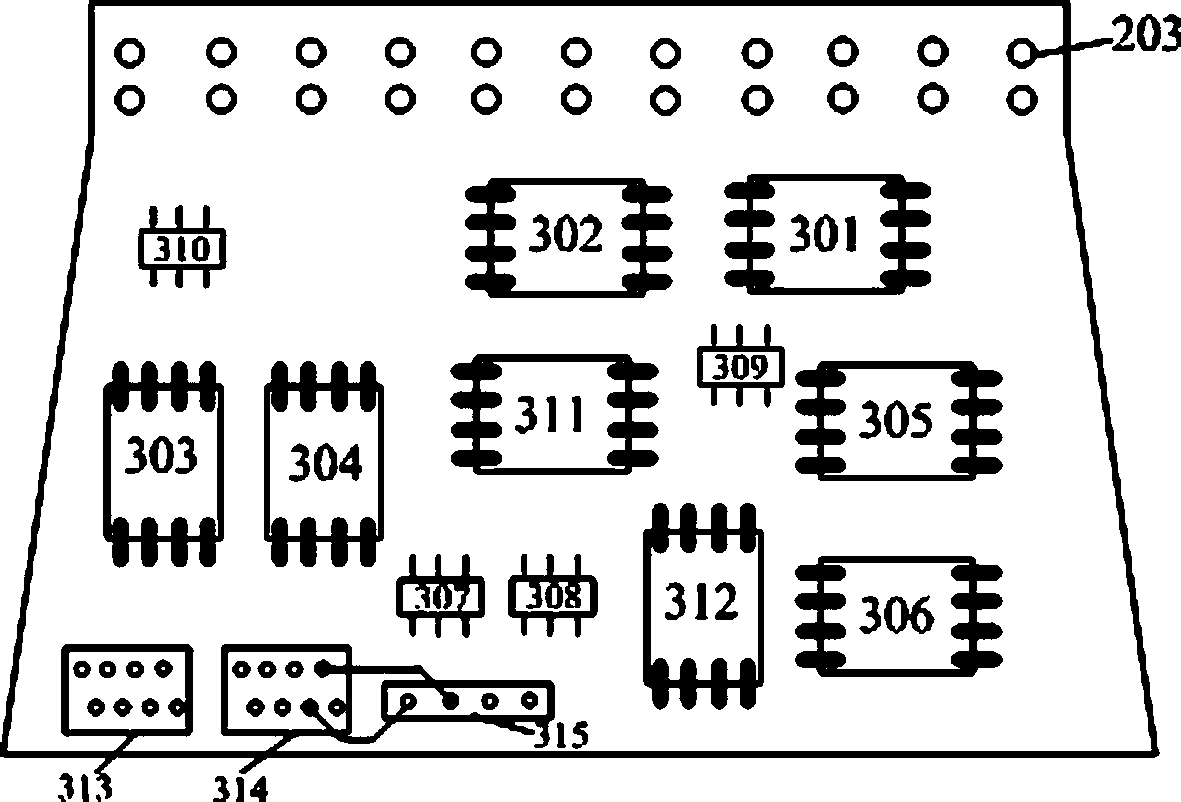

Image

  • Optical multi-point touch screen device and method applicable to vibration and damp environment
  • Optical multi-point touch screen device and method applicable to vibration and damp environment
  • Optical multi-point touch screen device and method applicable to vibration and damp environment

Examples


Embodiment Construction

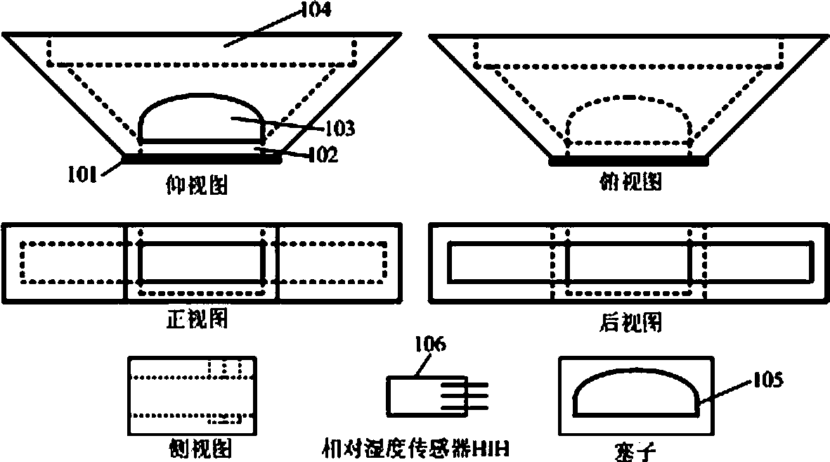
[0037] The technical solution of the present invention will be further described below in conjunction with the accompanying drawings.

[0038] At first the multi-point touch screen device of the present invention is illustrated in conjunction with the accompanying drawings:

[0039] figure 1 is a structural schematic diagram of an example of the trapezoidal box-shaped member for imaging of the present invention. The component includes: a transparent electrically-heatable glass sheet 101 coated with an extremely thin metal film on the surface, the glass sheet is mounted on the outside of the top edge of the trapezoidal box-shaped component and is well sealed with the trapezoidal box-shaped component; an infrared filter A sheet 102, the filter is installed between the electrically heatable glass sheet 101 and the convex cylindrical lens 103, which filters out visible light and allows near-infrared light between 800nm ​​and 1000nm to pass through; a piece of convex cylindrical l...


PUM


Abstract

The invention relates to an optical multi-point touch screen device and a method applicable to vibration and damp environment. The device comprises a screen, a touch screen frame and trapezoidal box-shaped components, wherein the touch screen frame is arranged on the outer edges of the screen, the trapezoidal box-shaped components are arranged at four corners of the screen frame, a linear array image sensor plate and a convex cylindrical lens are arranged in the components, and the sensor plate is connected with a driving plate through a connector. The optical multi-point touch screen device and the method have the advantages that the device is applicable to the modification of a plane large-screen display into a multi-point touch display, the problems of durability, light transmission rate and screen size limitation of a resistance screen and a capacitance screen are solved, the multi-point identification positioning method can be used for obtaining the center coordinates and the occupied regions of each touch point, in addition, ghost points can be effectively eliminated, the imaging characteristics of the convex cylindrical lens structure are adopted so that certain tolerance is realized on the vibration, in addition, the installation precision requirement on the structure is low, the imaging distortion is solved by adopting the optical calibration, the problems of high center precision and low peripheral precision of the screen of the triangular positioning method are avoided, a relative humidity sensor and electric heating glass are adopted, and the problem of optical touch screen failure caused by condensation in damp environment is avoided.

Description

technical field [0001] The present invention relates to the field of human-computer interaction technology and multi-point touch screen, in particular to a new type of man-machine that can identify and track multiple touch points and can identify and track multiple touch points, which is suitable for harsh environments such as vibration, humidity and condensation. An interactive device and a related positioning method. Background technique [0002] Currently, touch screen technology has been widely used in various electronic devices. Several multi-touch screen technologies have also emerged in recent years. With the development of technologies such as large-screen display and three-dimensional electronic sand table on military computer platforms, the requirements for new human-computer interaction equipment are getting higher and higher. Traditional interactive devices such as trackballs and keyboards can no longer meet the control requirements of the three-dimensional ele...

Claims


Application Information

Patent Timeline
Patent Type & Authority Patents(China)
IPC IPC(8): G06F3/042
Inventor 邵宏峰徐小梅黄涌覃岚
Owner NO 709 RES INST OF CHINA SHIPBUILDING IND CORP
Learn More