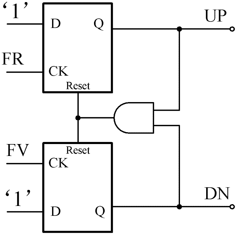
Fully differential frequency and phase detector with adjustable reset delay

A frequency and phase detector, full differential technology, applied in the direction of electrical components, power automatic control, etc., can solve the problems of four-way output pulse control signal mismatch, insufficient drive capability of the charge pump, uncontrollable reset delay time, etc. Achieve the effect of eliminating dead zone of phase identification, improving sensitivity and working speed, and eliminating stray

Inactive Publication Date: 2011-12-21
XIDIAN UNIV
View PDF1 Cites 23 Cited by
  • Summary
  • Abstract
  • Description
  • Claims
  • Application Information

AI Technical Summary

Problems solved by technology

[0011] To sum up, common frequency and phase detectors have the following disadvantages: the phase detection error is too large, the reset delay time is uncontrollable, the driving ability of the charge pump is insufficient, and the four output pulse control signals do not match.

Method used


Image

  • Fully differential frequency and phase detector with adjustable reset delay
  • Fully differential frequency and phase detector with adjustable reset delay
  • Fully differential frequency and phase detector with adjustable reset delay

Examples


Embodiment Construction

[0043] The frequency and phase detector of the present invention is applied in a phase-locked frequency synthesizer, adopts a TSMC 0.18μm RFCMOS1P6M process, and has a power supply voltage of 1.8V. In order to further illustrate the advantages of the present invention and the specific technical means adopted, the specific implementation and circuit structure of the present invention will be described in detail below in conjunction with the drawings.

[0044] refer to Figure 5 , the present invention consists of four fully differential RS flip-flops RS1, RS2, RS3 and RS4, two output buffer circuits buffer1 and buffer2, a fully differential four-input NAND gate G0 for generating reset signals and a delay control circuit DL composition. in:

[0045] The fully differential RS flip-flop RS1 is composed of a two-input fully differential NAND gate G1 and a two-input fully differential NAND gate G2. Input fully differential NAND gate G4 is composed of input and output cross-coupli...


PUM


Abstract

The invention discloses a fully differential reset delay adjustable frequency and phase discriminator, which comprises four RS triggers, nand gates G0, a delay control circuit DL and two output buffer circuits, wherein all the four RS triggers have the structures that two nand gates are crossed and coupled; all nand gates are fully differential static CMOS (Complementary Metal Oxide Semiconductor) logics with positive feedback; the DL delay circuit is formed by cascading three delay fixed units and three delay controllable units; and each buffer circuit is formed by cascading fully differential phase inverters with transistors of multiplied sizes and positive feedback. Reset signals generated by the nand gates G0 are delayed by the DL circuit to perform reset control on the four RS triggers; and four paths of pulse control signals are output by the second RS trigger and the fourth RS trigger through the buffer circuits which are connected with the second RS trigger and the fourth RS trigger respectively. The discriminator has the advantages of small phase discrimination error, controllable reset delay, high driving capacity and high matching degree output of the four paths of pulse control signals and can be used for a high-performance phase locked frequency synthesizer.

Description

technical field [0001] The invention belongs to the technical field of integrated circuit design and relates to a phase-locked frequency synthesizer circuit, in particular to a frequency and phase detector with an adjustable reset delay of a fully differential structure, which can be used in a frequency synthesizer of a radio frequency front-end receiver system. Background technique [0002] At present, the phase-locked frequency synthesizer is widely used in the fields of electronic communication and radio frequency technology, and has become an indispensable basic module in various electronic equipment and communication equipment. Such as figure 1 As shown, the phase-locked frequency synthesizer is composed of a frequency detector, a charge pump, a loop filter, a voltage-controlled oscillator and a frequency divider. The frequency and phase detector compares the frequency and phase of the input reference signal and the output signal of the frequency divider, and generates...

Claims


Application Information

Patent Timeline
Patent Type & Authority Applications(China)
IPC IPC(8): H03L7/085
Inventor 庄奕琪李振荣朱新亮靳刚汤华莲李聪曾志斌
Owner XIDIAN UNIV
Why Eureka
Try Eureka