Device and method for burning catalyst of fixed bed reactor

A fixed-bed reactor and catalyst technology, which is applied in chemical instruments and methods, catalyst regeneration/reactivation, physical/chemical process catalysts, etc., can solve the problems of high energy consumption, slow speed, long time, etc., and achieve improved coking strength, avoid local overheating, and reduce energy consumption

Active Publication Date: 2013-06-19
HENGQIN INT INTPROP EXCHANGE CENT CO LTD
View PDF1 Cites 0 Cited by
  • Summary
  • Abstract
  • Description
  • Claims
  • Application Information

AI Technical Summary

Problems solved by technology

These two methods have a common disadvantage when applied to a fixed-bed reactor with a multi-stage catalyst bed structure: that is, there is only one entrance for the charred medium to enter the reactor, whether it enters from the top of the reactor or from the bottom, it is layer by layer forward. Propulsion, slower speed, longer time, higher energy consumption

Method used


Image

  • Device and method for burning catalyst of fixed bed reactor

Examples


Embodiment 1

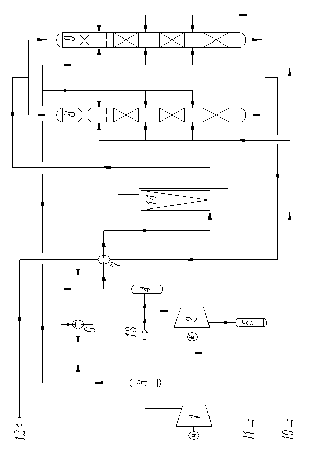
[0019] Embodiment 1, a catalyst coking device for a fixed bed reactor, the fixed bed reactor contains four sections of catalyst beds, and the side wall of the reactor between adjacent beds is provided with three-way side inlet pipes; Reactor (8 and 9), heating furnace 14, gas compressor 1, heat exchanger 7, cooler 6, buffer tank (3, 4 and 5), nitrogen compressor 2 and condensed water 10, nitrogen 11, excess smoke Gas 12 and steam 13 are connected through pipelines and control valves to form a multi-channel temperature control system: one channel includes nitrogen compressor 2, heat exchanger 7, heating furnace 14, fixed bed reactor (8 and 9) top inlet pipe, fixed bed Reactors (8 and 9) are connected to the bottom outlet pipe, heat exchanger 7, and cooler 6 in sequence, and then return to the flue gas temperature-regulating closed cycle system of nitrogen compressor 2; the second path includes nitrogen compressor 2, fixed-bed reactor ( 8 and 9) The side inlet pipe, the fixed be...

Embodiment 2

[0020] In Example 2, on the basis of Example 1, condensed water nozzles are provided on the side wall of the reactor between adjacent beds, and all nozzles are connected to the water inlet pipe 10 through control valves. A pressure control valve is provided on the discharge branch line 12 of the outlet pipeline of the hot flue gas heat exchanger 7 . Also be connected with steam pipe 13 on the surge tank of nitrogen compressor.

Embodiment 3

[0021] Embodiment 3, according to the fixed bed reactor catalyst coking method of the device of embodiment 1, first utilize nitrogen compressor 2 to send nitrogen successively into heat exchanger 7, heating furnace 14, fixed bed reactor (8 and 9), After the heat exchanger 7 and the cooler 6, return to the nitrogen compressor 2 to establish a nitrogen cycle; after that, the heating furnace 14 heats the nitrogen cycle, and the heating rate is maintained at 30~40°C / h, and the fixed bed reactor (8 and 9) exits When the temperature reaches 250°C, start the air compressor 1. One way of air merges with the flue gas from the outlet pipe of the nitrogen compressor 2 and directly flows into the inlet pipe on the side wall of the reactor. The other way of air slowly injects air into the regeneration process of the outlet pipe of the cooler 6. Gradually raise the temperature to 350°C and keep the temperature constant. During the process of constant temperature at 350°C, control the tempera...


PUM


Abstract

The invention provides a device and method for burning a catalyst of a fixed bed reactor. The device comprises the fixed bed reactor, a heating furnace, a gas compressor, a heat exchanger, a cooler, a pipeline and a control valve unit, wherein the pipeline is connected with the control valve unit to form a multipath temperature control system. The method mainly comprises the following steps: hightemperature burning medium passing through the heating furnace enters from the top part of the fixed bed reactor, high temperature burning smoke coming out from a first section of a catalyst bed layer is mixed with low-temperature burning medium from an intersectional distributor before the high temperature burning smoke enters a second section of the catalyst bed layer, and the process is repeated until the high temperature burning smoke coming out from the last section of the catalyst bed layer comes out from the reactor. The device and method provided by the invention have the main advantages of being beneficial to the utilization of heats produced by the burning, reducing the energy consumption of the heating furnace, improving the burning strength, shortening the burning time and being convenient for thee temperature control of the catalyst bed layer.

Description

technical field [0001] The invention relates to a catalyst coking device and method for a fixed-bed reactor, which is particularly suitable for coking of catalysts including olefins in catalytic cracking and delayed coking dry gas and olefins in liquefied gas for gasoline and other fixed-bed catalysts. Background technique [0002] The fixed-bed reactors that use catalytic cracking and delayed coking dry gas as raw materials are mostly vertical tank structures with a single-stage catalyst bed. The top of the reactor is equipped with feed pipes and distributors; the internal space of the reactor is filled with the required catalyst to form a catalyst bed. With the development of catalyst and process, equipment and control technology, the catalyst bed in the fixed bed reactor has recently changed from one-stage bed to multi-stage bed structure. For example, the patent application for "Aromatization Reactor" (Application No.: 201110059525.9) previously proposed by the applican...

Claims


Application Information

Patent Timeline
Patent Type & Authority Patents(China)
IPC IPC(8): B01J38/14B01J38/02
Inventor 何燕文高玉玲
Owner HENGQIN INT INTPROP EXCHANGE CENT CO LTD
Why Eureka
Try Eureka