
A forging method for preventing cracks in hot forging of mn18cr18n steel retaining ring

A technology of hot forging and cracking, which is applied in the field of forging to prevent cracks from hot forging of Mn18Cr18N steel retaining rings. Forming force, effect of preventing cracks

Inactive Publication Date: 2011-12-28
TAIYUAN UNIVERSITY OF SCIENCE AND TECHNOLOGY
View PDF4 Cites 16 Cited by
  • Summary
  • Abstract
  • Description
  • Claims
  • Application Information

AI Technical Summary

Problems solved by technology

For example, ZL200510012565.2 "A Method and Die for Making Hot Forging Ring Blank of Generator Guard Ring" has many outstanding advantages compared with the free forging method, but this method requires a large tonnage of equipment, and the process methods and molds used are also very complicated. , inconvenient to use

Method used


Image

  • A forging method for preventing cracks in hot forging of mn18cr18n steel retaining ring
  • A forging method for preventing cracks in hot forging of mn18cr18n steel retaining ring
  • A forging method for preventing cracks in hot forging of mn18cr18n steel retaining ring

Examples


Embodiment Construction

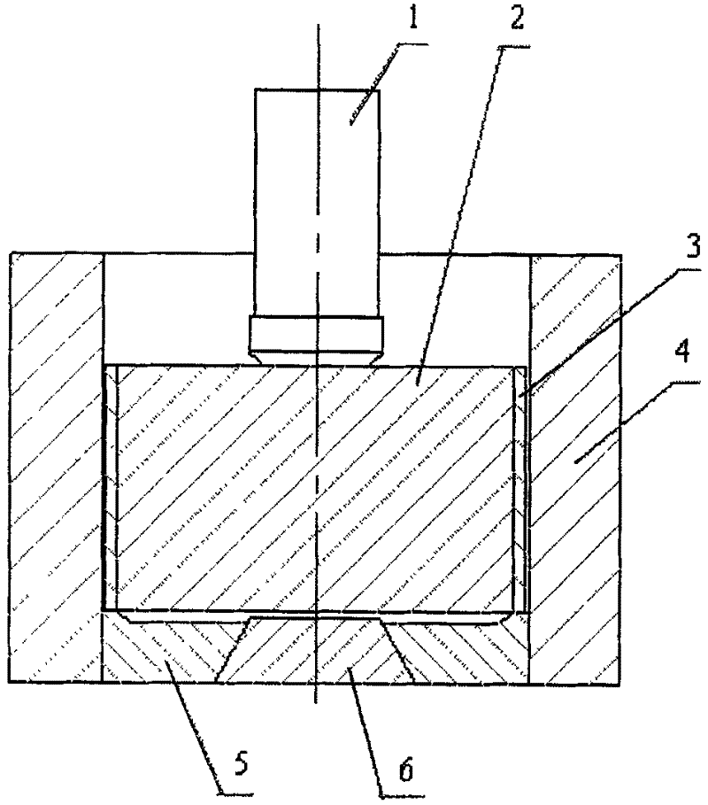
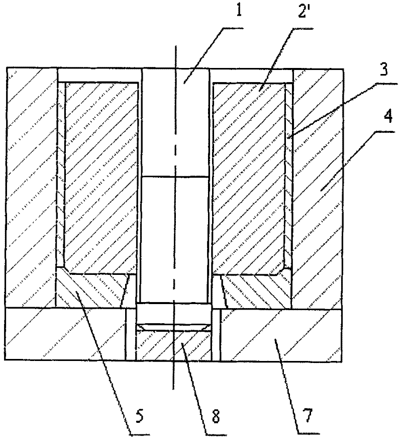
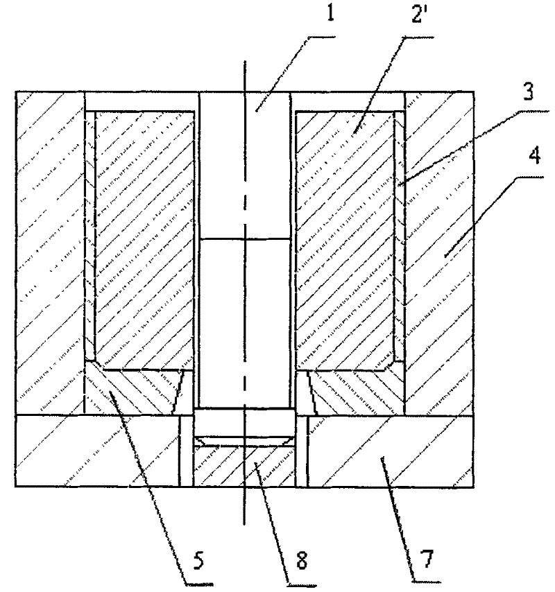
[0017] Now take the production of a forging of a retaining ring whose material is Mn18Cr18N steel and whose size is φ990×φ640×990mm as an example, the diameter of the punch is set to d=430mm, and the diameter of the small end of the 5 taper holes at the bottom of the mold is d 1 =460mm, leakage disk 7 hole diameter d 2 =460mm, billet diameter D=1030mm, the forging process method is:

[0018] (1) Boss 6 is placed in the conical hole in the bottom mold 5 middle part, and it is placed together in a tubular barrel mold 4 inner bottom;

[0019] (2) A tubular sheath 3 made of 20 steel is tightly placed on the outside of the billet 2 with a diameter of D=1030mm, and heated together to 1150°C, the wall thickness of the sheath 3 is 36mm;

[0020] (3) Place the heated blank 2 and the sheath 3 together in the barrel mold 4, the gap δ=50mm between the outer surface of the sheath 3 and the inner surface of the barrel mold 4, use a punch equipped with a locator 1 Punch the blank 2 from th...


PUM


Abstract

The invention relates to a forging method for preventing cracks from being generated by the hot forging of a Mn18Cr18N steel protecting ring, which belongs to the technical field of the hot-forging formation of alloy steel. Used devices comprise a boss, a bottom die, a cylinder die, a punching head and a leaking disk. The forging method for preventing the cracks from being generated by the hot forging of the Mn18Cr18N steel protecting ring is characterized in that the forging method comprises the following steps: (1) placing the boss in a conical hole of the bottom die and placing the boss and the bottom die at the inner bottom of the cylinder die together; (2) sleeving a wrapping sleeve outside a blank tightly and heating the wrapping sleeve and the blank to 950 to 1200 DEG C together; (3) placing the blank and the wrapping sleeve which are heated in the cylinder die, and carrying out impact extrusion on the blank from the top by using the punching head so as to reach the designed depth, wherein the difference delta of the outer diameter of the wrapping sleeve and the inner diameter of the cylinder die is equal to 0.03D to 0.10D; (4) removing the boss and replacing by the leakingdisk; (5) stamping the blank continuously by using the punching head, and stamping off burrs at the bottom of the blank; and (6) quitting the punching head and taking out an annular forged piece so as to finish the operations of punching and forming. The forging method for preventing the cracks from being generated by the hot forging of the Mn18Cr18N steel protecting ring has the following advantages that: (1) a clearance is remained between the wrapping sleeve and the cylinder die, so that the cracks generated at the surface of the forged piece can be prevented, and the tonnage of required equipment can also be decreased; and (2) crystal grains inside the forged piece can be thinned.

Description

technical field [0001] The invention belongs to the technical field of alloy steel hot forging, and in particular relates to a forging method for preventing cracks from hot forging of Mn18Cr18N steel retaining rings. Background technique [0002] The retaining ring is one of the large key parts of thermal power equipment. It not only bears huge centrifugal force during high-speed rotation, but also bears thermal loading stress, alternating stress, and bending stress. It requires sufficient strength, good toughness, Uniform mechanical properties, minimum residual stress, and the guard ring works in a strong magnetic field and a corrosive atmosphere. Therefore, it is also required to be non-magnetic and have high stress corrosion resistance. At present, the method of forging retaining ring parts at home and abroad generally adopts the process of heating and forging a ring blank from a steel ingot, and then making a forging through a process of solid solution treatment and cold...

Claims


Application Information

Patent Timeline
IPC IPC(8): B21J5/10
Inventor 张秀芝刘建生段兴旺何文武
Owner TAIYUAN UNIVERSITY OF SCIENCE AND TECHNOLOGY
Learn More