A diesel engine scr urea injection device

A technology of urea injection and diesel engine, which is applied in the direction of mufflers, exhaust devices, mechanical equipment, etc., can solve the problems affecting the precision and accuracy of injection metering, large fluctuations in diesel engine exhaust pressure, poor accuracy and stability, etc., to achieve Effects of light weight, easy control, and improved reliability

Active Publication Date: 2011-12-28
ZHEJIANG BONDLYE ENVIRONMENTAL TECH CO LTD
View PDF5 Cites 11 Cited by
  • Summary
  • Abstract
  • Description
  • Claims
  • Application Information

AI Technical Summary

Problems solved by technology

[0003] In the current SCR injection urea solution system, the urea electromagnetic nozzle is often installed directly on the exhaust pipe. Since the electromagnetic nozzle is an electronic component, the high exhaust temperature of the engine will cause damage to the urea electromagnetic nozzle, and the urea electromagnetic nozzle must be cooled.
The disclosed technology uses urea solution to cool the urea electromagnetic nozzle. After the urea solution exchanges heat with the electromagnetic nozzle and the exhaust pipe, the temperature will inevitably rise, resulting in a change in the density of urea and affecting the precision and accuracy of injection metering. The effect requires cooling of the urea solution or changing the injection metering according to the change of urea density
[0004] In addition, the urea electromagnetic nozzle is often directly installed in the exhaust pipe, and the exhaust pressure of the diesel engine fluctuates greatly. The urea injection system lacks effective measures to stabilize the pressure wave in the pipeline in front of the urea electromagnetic nozzle, resulting in large fluctuations in the injection volume of urea. Accuracy and Poor stability

Method used


Image

  • A diesel engine scr urea injection device
  • A diesel engine scr urea injection device

Examples


Embodiment Construction

[0019] The present invention will be further described below in conjunction with the accompanying drawings.

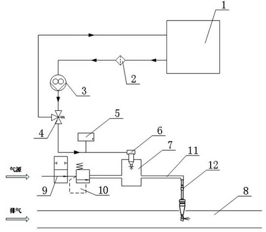
[0020] As shown in the figure, a diesel engine SCR urea injection device includes a mixing chamber 7 on which a gas source inlet, a urea inlet and a liquid outlet pipe 11 are arranged.

[0021] The air source inlet of the mixing chamber 7 is sequentially connected with an air pressure stabilizing valve 10 and an air solenoid valve 9 .

[0022] A nozzle 6 is fixedly arranged on the urea inlet of the mixing chamber 7 , and the nozzle 6 is placed in the inner cavity of the mixing chamber 7 . The pipeline on the nozzle 6 is connected to the safety pressure limiting valve 4, which is a mechanical pressure limiting valve, and one end of the safety pressure limiting valve 4 is connected to the urea tank 1 at the same time; the pipeline of the safety pressure limiting valve 4 is connected to the gear pump 3. The gear pump 3 is a magnetic gear pump driven by a 24V DC power sup...


PUM


Abstract

The invention discloses a selective catalytic reduction (SCR) urea jet device of a diesel engine, and belongs to the technical field of engine exhaust purification treatment. The SCR urea jet device comprises a mixing cavity; the mixing cavity is provided with a gas source inlet, a urea inlet and a liquid outlet pipe; the gas source inlet is sequentially connected with an air pressure maintainingvalve and an air electromagnetic valve through pipelines; a nozzle is fixedly arranged on the urea inlet; the nozzle is sequentially connected with a safety pressure limiting valve, a gear pump, a urea filter and a urea tank through pipelines; the tail end of the liquid outlet pipe is connected with a mechanical atomizer; and the atomizer is arranged on an exhaust pipe of the external diesel engine. The SCR urea jet device of the diesel engine has simple structure and is reasonable in design. Quantitative jet of aqueous solution of urea is realized through the electromagnetic nozzle; and meanwhile, the urea corrosion and high temperature resistant mechanical atomizer is directly arranged on the high temperature exhaust pipe by adopting an air assisting mode, so that the reliability of thesystem is promoted.

Description

technical field [0001] The invention belongs to the technical field of engine emission purification treatment, in particular to a method for reducing diesel engine NO x Selective Catalyst Reduction system (Selective Catalyst Reduction) urea quantitative injection device. Background technique [0002] Since its inception, diesel engines have been widely used in various power plants, ships and vehicles due to their good power, economy and durability. Particulate matter (PM) and nitrogen oxides (NOx) for diesel engines x ) are two major pollutants that are purified by various methods. Among them, SCR technology is currently used to reduce diesel engine NO x A very effective method of emission. Diesel engine SCR post-treatment technology uses urea aqueous solution as a reducing agent to inject into the exhaust of diesel engines. Under the action of exhaust gas temperature and air flow, urea releases ammonia (NH 3 ), and at a certain temperature and under the action of a cat...

Claims


Application Information

Patent Timeline
Patent Type & Authority Applications(China)
IPC IPC(8): F01N3/24
Inventor 陈法献
Owner ZHEJIANG BONDLYE ENVIRONMENTAL TECH CO LTD
Why Eureka
Try Eureka