An ultra-low temperature exhaust gas energy-saving boiler
A technology for ultra-low temperature and boilers, applied in lighting and heating equipment, etc., can solve the problems of low fuel utilization efficiency, high carbon content in fly ash, high dust concentration, etc., to improve utilization rate, reduce SOx content, and improve boiler energy efficiency Effect
- Summary
- Abstract
- Description
- Claims
- Application Information
AI Technical Summary
Problems solved by technology
Method used
Image
Examples
specific Embodiment approach 1
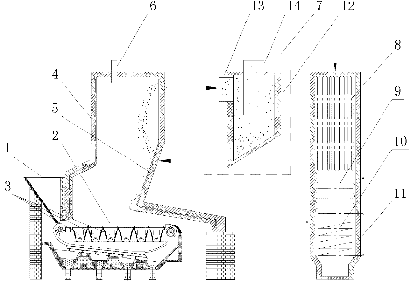
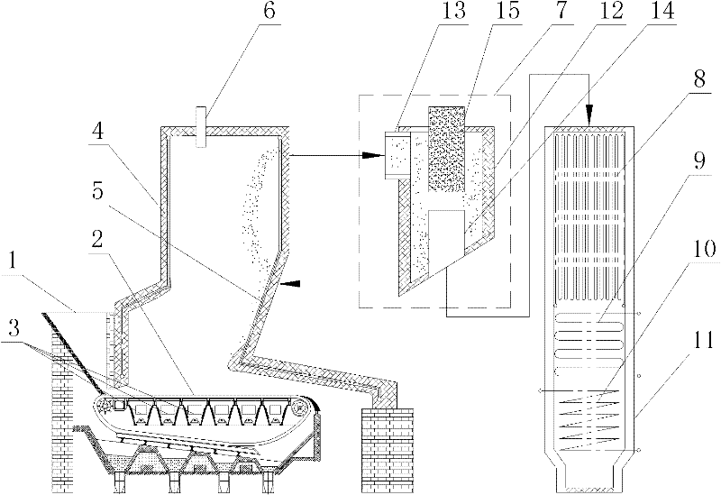
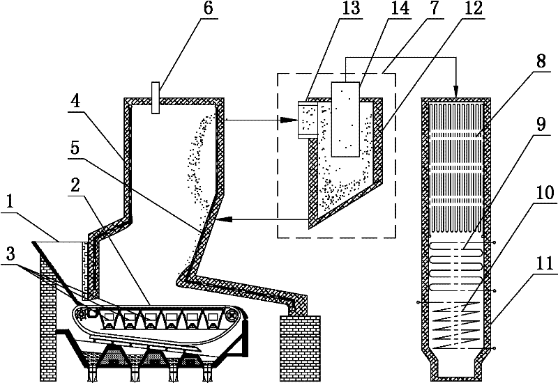
[0015] Specific implementation mode one: as Figure 1~2 As shown, an ultra-low temperature smoke exhaust energy-saving boiler in this embodiment includes a coal hopper 1, a fire grate 2, an air supply bin 3, a furnace body 4, a rear arch 5, a convection tube bundle 8, an economizer 9, and an air preheater 10 and vertical flue 11, the coal scuttle 1 is arranged on the front wall of the furnace body 4, the lower end of the coal scuttle 1 communicates with the furnace body 4, the rear arch 5 is arranged on the rear wall of the furnace body 4, the Fire grate 2 is located in furnace body 4, and described fire grate 2 is positioned at the below of coal hopper 1 and rear arch 5, and the bottom of described fire grate 2 is provided with a plurality of air-supply bins 3, and described a plurality of air-supply bins 3 all It communicates with the air preheater 10, the convection tube bundle 8, the economizer 9 and the air preheater 10 are sequentially arranged in the vertical flue 11 fr...
specific Embodiment approach 2
[0016] Specific implementation mode two: as figure 1 As shown, the cyclone dust collector 7 in this embodiment is composed of a dust collector main body 12, an inlet pipe 13 and an outlet pipe 14. The inlet pipe 13 is arranged on the side wall of the dust collector main body 12. The upper end of the main body 12 is connected, the outlet pipe 14 is vertically inserted on the upper surface of the dust collector main body 12, the lower end of the outlet pipe 14 is lower than the inlet pipe 13, and the bottom end surface of the dust collector main body 12 is an inclined plane. Such a design makes the flue gas at the outlet of the boiler furnace enter from the inlet pipe 13 of the cyclone dust collector and flows around the outlet pipe 14, thereby generating a complex vortex field in the cyclone dust collector 7 and realizing gas-solid separation in the cyclone dust collector At the same time, it also causes a strong gas-solid interaction, which is conducive to the full and efficie...
specific Embodiment approach 3
[0017] Specific implementation mode three: as figure 2 As shown, the cyclone dust collector 7 in this embodiment is composed of a dust collector main body 12, an inlet pipe 13, an outlet pipe 14 and a spin column 15. The inlet pipe 13 is arranged on the side wall of the dust collector main body 12. The swivel column 15 is vertically inserted on the upper end surface of the dust collector main body 12, the outlet pipe 14 is located in the dust collector main body 12, the outlet pipe 14 communicates with the lower end of the dust collector main body 12, and the lower end of the outlet pipe 14 is fixed On the bottom end surface of the dust collector main body 12, the bottom end surface of the dust collector main body 12 is a slope. Such a design makes the flue gas at the outlet of the boiler furnace enter from the inlet pipe 13 of the cyclone dust collector, and flows around the swivel column 15, thereby generating a complex vortex field in the cyclone dust collector 7, and real...
PUM
 Abstract
Description
Claims
Application Information
 - R&D
- Intellectual Property
- Life Sciences
- Materials
- Tech Scout
- Unparalleled Data Quality
- Higher Quality Content
- 60% Fewer Hallucinations
Browse by: Latest US Patents, China's latest patents, Technical Efficacy Thesaurus, Application Domain, Technology Topic, Popular Technical Reports.
© 2025 PatSnap. All rights reserved.Legal|Privacy policy|Modern Slavery Act Transparency Statement|Sitemap|About US| Contact US: help@patsnap.com


