Device and method for integrally machining and measuring optical parts

A technology for optical parts and manufacturing devices, which is applied in the direction of manufacturing tools, metal processing equipment, metal processing machinery parts, etc., can solve the problems of unsatisfactory online measurement and low processing efficiency, and achieve the reduction of intermediate detection links, high processing efficiency and high processing efficiency. high precision effect

Active Publication Date: 2012-01-04
HARBIN INST OF TECH
View PDF6 Cites 22 Cited by
  • Summary
  • Abstract
  • Description
  • Claims
  • Application Information

AI Technical Summary

Problems solved by technology

[0012] The purpose of the present invention is to solve the problem that most of the existing optical parts processing adopts off-line measurement mode, and the processing efficiency is low; the existing optical parts processing equipment cannot meet the requirements of online measurement, and provides an integrated manufacturing device for optical parts processing and detection and manufacturing method

Method used


Image

  • Device and method for integrally machining and measuring optical parts
  • Device and method for integrally machining and measuring optical parts
  • Device and method for integrally machining and measuring optical parts

Examples


specific Embodiment approach 1

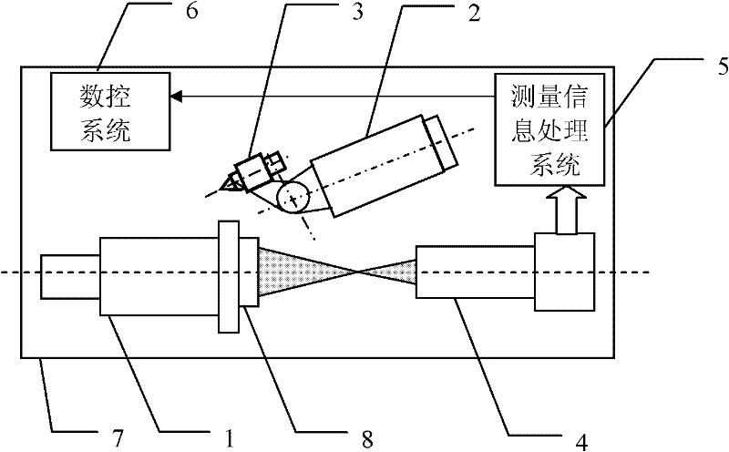
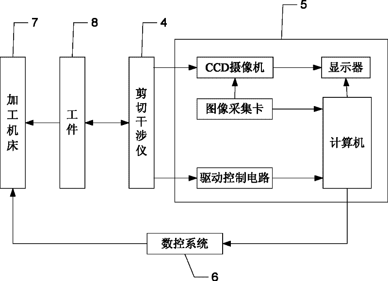
[0035] Specific implementation mode 1: the following combination figure 1 To explain this embodiment, the optical component processing and inspection integrated manufacturing device described in this embodiment includes a workpiece spindle 1, a tool spindle 2, a tool 3, a shearing interferometer 4, a measurement information processing system 5, and a numerical control system 6. , Where the workpiece spindle 1, the tool spindle 2 and the shearing interferometer 4 are installed on the work surface of the processing machine tool 7, the workpiece spindle 1 is installed with the workpiece 8, the tool spindle 2 is installed with the tool 3 through the swing arm and the tool post, and the CNC system 6 is driven The tool spindle 2 rotates, and at the same time it drives the tool spindle 2 to swing and drives the tool 3 to process the workpiece 8.

[0036] The center line of the shearing interferometer 4 is on the same line as the center line of the workpiece spindle 1, the shearing interf...

specific Embodiment approach 2

[0042] Embodiment 2: The difference between this embodiment and the first embodiment is that the radius of the tip arc of the tool 3 is 5 mm, and the rest is the same as the first embodiment.

specific Embodiment approach 3

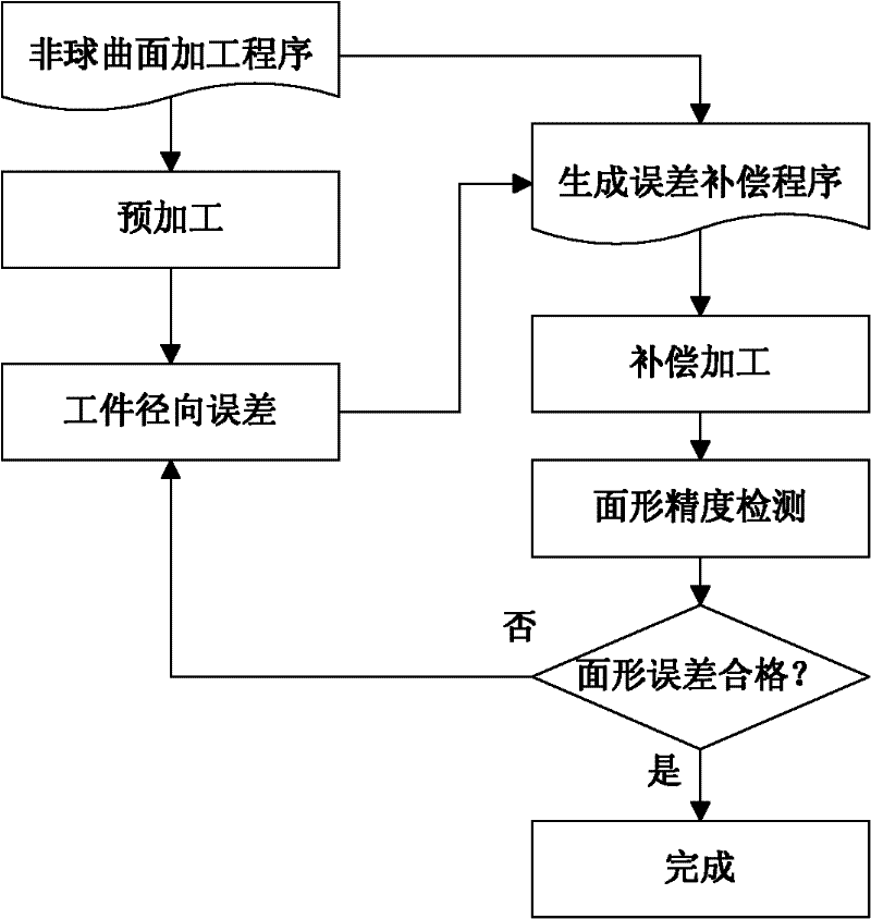
[0043] Specific implementation manner three: the following combination figure 2 , image 3 , Figure 4 with Image 6 To describe this embodiment, this embodiment is to realize the manufacturing method of the optical component processing and inspection integrated manufacturing device described in Embodiment 1. The method includes the following steps:

[0044] Step 1: Pre-processing; then, the tool spindle 2 drives the swing arm and the tool 3 to rotate 90° to give up the detection light path;

[0045] Step 2. The shearing interferometer 4 sends out the detection beam to the workpiece 8. The shearing interferometer 4 collects the image information returned by the detection beam and sends it to the measurement information processing system 5. The measurement information processing system 5 obtains the workpiece 8 according to the image information Surface shape error information;

[0046] Step 3: Determine whether the surface shape error information meets the accuracy requirements set ...


PUM

PropertyMeasurementUnit
radiusaaaaaaaaaa

Abstract

The invention relates to a device and method for integrally machining and measuring optical parts, belonging to the field of optical part machining. The invention aims at solving the problems that: an off-line measuring manner is mostly adopted in the traditional optical part machining, thus the machining efficiency is low; and the traditional optical part machining equipment cannot satisfy with the requirement of online measuring. According to the invention, a workpiece main shaft, a cutting tool main shaft and a shearing interferometer are mounted on a worktable surface of a machining machine; a workpiece is mounted on the workpiece main shaft; a cutting tool is mounted on the cutting tool main shaft through an oscillating arm and a tool carrier; a numerical control system is used for driving the cutting tool main shaft to rotate and driving the cutting tool to machine the workpiece; the optical axis of a measuring light beam which is emitted by the shearing interferometer and the central line of the workpiece main shaft are the same straight line; the shearing interferometer is used for emitting the measuring light beam to the workpiece; the shearing interferometer is used for acquiring image information which is returned by the measuring light beam and is used for sending the image information to a measured information processing system; the measured information processingsystem is used for acquiring surface error information of the surface of the workpiece according to the image information and is used for sending the information to the numerical control system; and the numerical control system is used for carrying out compensation machining on the workpiece.

Description

Technical field [0001] The invention relates to an integrated manufacturing device and method for processing and detecting optical parts, and belongs to the field of optical parts processing. Background technique [0002] Various spherical and aspherical optical parts are commonly used parts for optical systems such as cameras, CCDs, medical instruments, measuring instruments, space detectors, astronomical telescopes, etc., which have a large and wide range of application requirements. At present, not only high manufacturing accuracy is required, but also the demand It is also very large, so it requires efficient processing and manufacturing. [0003] With the development of modern optical processing technology, high-quality optical mirror parts can be processed internationally using a variety of processing techniques. Using single point diamond turning, numerical control grinding, computer-controlled small grinding head grinding and polishing, active disk technology, beam energy ...

Claims


Application Information

Patent Timeline
Patent Type & Authority Applications(China)
IPC IPC(8): B23P17/00B23Q17/20G05B19/18
Inventor 孙涛王起维韩成顺张龙江李国董申
Owner HARBIN INST OF TECH
Why Eureka
Try Eureka